
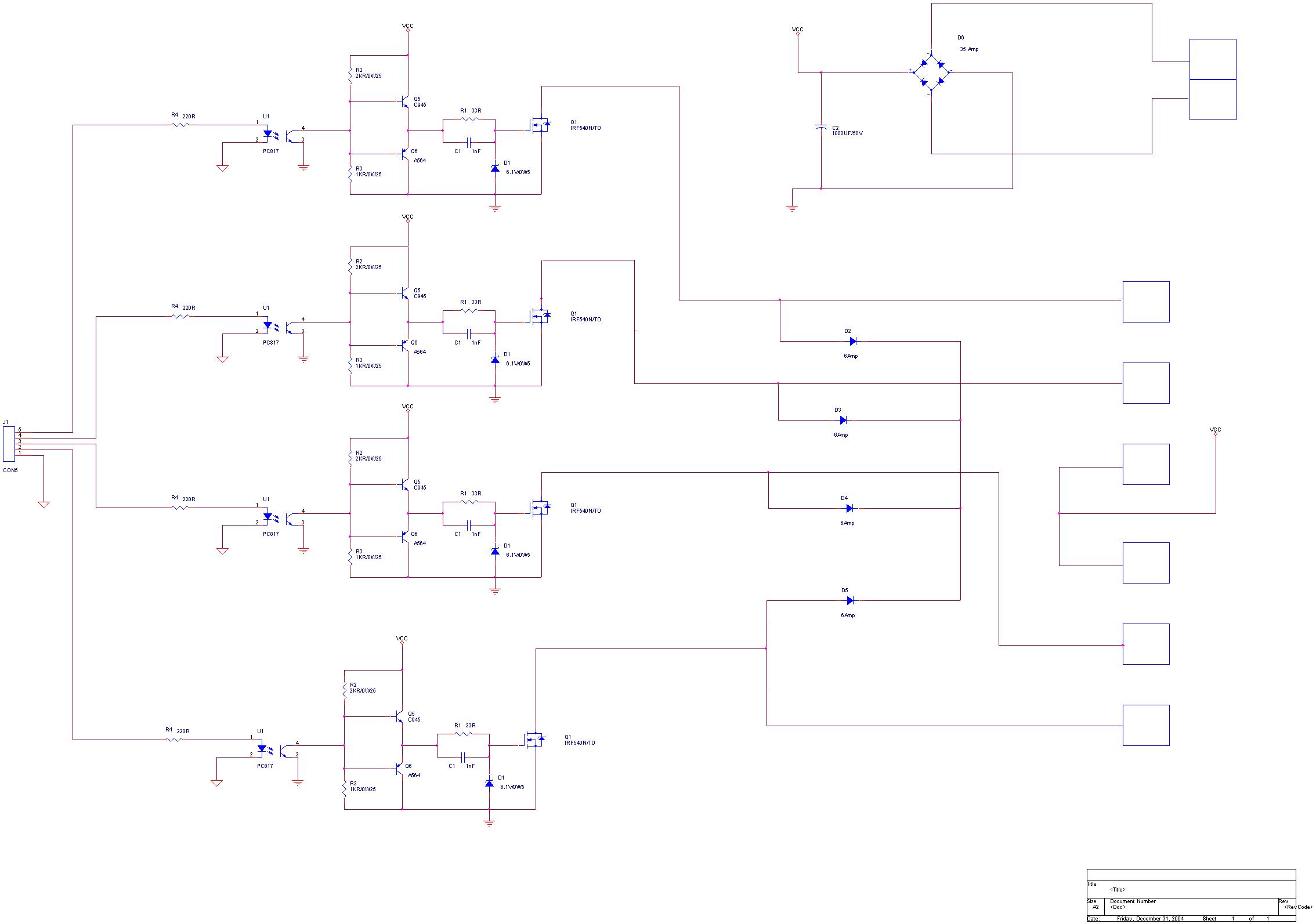
Current spreading circuit diagram of a bipolar output

The circuit described involves a current spreading bipolar output configuration. This type of circuit is typically used in applications requiring efficient current distribution across multiple output paths, often seen in power amplification and driving loads in electronic systems.
In a current spreading bipolar output circuit, bipolar junction transistors (BJTs) are utilized to achieve the desired output characteristics. The circuit design may include a differential input stage that amplifies the input signal and drives the output stage composed of multiple BJTs configured in parallel. This configuration allows for the sharing of current among the transistors, thereby improving reliability and thermal performance.
The circuit diagram may feature a biasing network that ensures the transistors operate in their active region, preventing cutoff or saturation during signal processing. Resistors may be employed for emitter degeneration to improve linearity and stability, while capacitors can be included for AC coupling or bypassing to filter out noise.
The output stage may be designed to drive various loads, such as speakers or other electronic components, with the ability to handle significant current levels. Feedback mechanisms could be incorporated to enhance the performance by reducing distortion and improving frequency response.
Overall, the current spreading bipolar output circuit is a robust design choice for applications demanding high performance and efficiency in current handling.Current spreading bipolar output when the circuit diagram is as follows:
Related Circuits
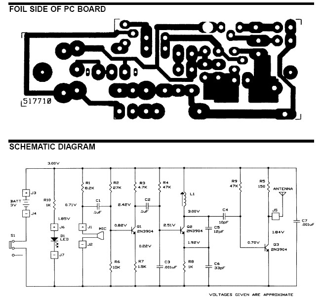
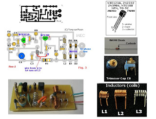
The frequency range for the FM transmission band is 90 MHz (megahertz, or 90 million cycles per second). Due to the variable tuned circuit in the FM transmitter, it can be tuned to a specific frequency within the local...
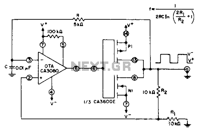
CA3600E array transistor pair and a reverse CA3080 operational amplifier are used together to provide precise timing and thresholds for the square wave. A typical static power consumption is 6mW. The CA3600E is a versatile integrated circuit that includes multiple...
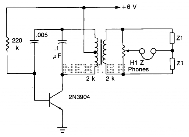
The transistor is configured as an audio oscillator, utilizing an audio transformer in the collector. The secondary winding is connected to a linear potentiometer. The ratio between the two sections of the potentiometer from the slider is proportional to...
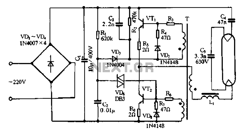
Bridge rectifier circuit in the electronic ballast application circuit The bridge rectifier circuit is a crucial component in electronic ballast applications, primarily utilized for converting alternating current (AC) to direct current (DC). This conversion is essential for powering various electronic...
A circuit has been constructed based on a design from Silicon Chip magazine to test bipolar stepper motor collections. The circuit is easy to build and functions effectively. The described circuit is designed to facilitate the testing of bipolar stepper...
The FM telephone circuit is constructed on a compact PC board that can be easily integrated into the housing of a telephone, functioning as a pseudo-speak earphone. This FM circuit connects in series with the telephone line, drawing power...