
A Hartley Oscillator

The Hartley oscillator is a type of electronic oscillator that generates sinusoidal waveforms. It is characterized by its feedback mechanism, which relies on the inductive coupling of a single coil. The coil is typically divided into two sections, with the feedback being taken from a tap point that can be adjusted to optimize performance. This tap allows for fine-tuning of the oscillation frequency by altering the degree of coupling between the two parts of the coil.
The configuration of the circuit as a parallel-feed type is significant because it allows for the separation of AC and DC components. The choke coil, which is an inductor, serves to block high-frequency AC signals from flowing into the DC path, ensuring that the direct current remains stable and unaffected by the oscillations. Conversely, the blocking condenser prevents any DC voltage from affecting the AC circuit, maintaining the integrity of the oscillation.
In addition to the choke coil and blocking condenser, the grid condenser and grid-leak resistor are essential components that influence the oscillator's performance. The grid condenser acts as a coupling capacitor, allowing AC signals to pass while blocking DC. The grid-leak resistor provides a path for the DC biasing of the grid, ensuring that the transistor or vacuum tube operates within its active region. Together, these components contribute to the overall stability and efficiency of the Hartley oscillator, making it a popular choice in various RF applications, including signal generation and amplification in communication systems.In the Hartley circuit (Fig. 14 B), the amplified energy of the plate circuit is fed back to the grid circuit by means of fluctuating magnetic fields. They are both of the so-called magnetic feedback type. The Hartley circuit uses only one coil, part of which is in the plate circuit and part in the grid ci
rcuit. The amount of magnetic coupling between the two parts of the coil is adjusted by moving the tap. This tap is indicated by the arrowhead in Fig. 14 B. The circuit shown is of the so-called parallel-feed type. In other words, the plate circuit is divided into two parallel branches, one of which carries the direct current and the other the alternating current. A choke coil (r. f. c. ) keeps the alternating current out of the d. c. path, and a blocking condenser Cb keeps the d. c. out of the a. c. circuit. The grid condenser Cg and the grid-leak resistor Rg serve the same purpose as in the tickler circuit.
🔗 External reference
Related Circuits
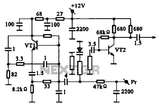
The local oscillator operates at frequencies of 1 GHz or higher, utilizing a common collector circuit, which makes it challenging to generate low-frequency self-oscillation. Typically, the local oscillator signal is passed through a buffer amplifier stage before being applied...
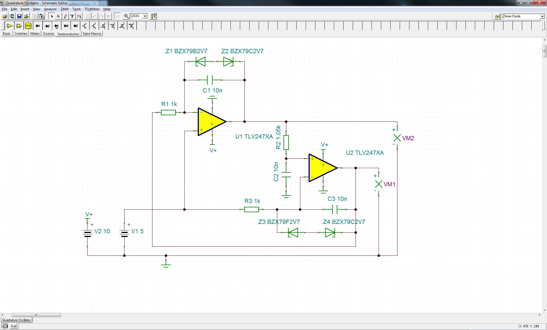
The circuit is close to sustaining oscillation. Changing resistor R2 to 10.5k will enable it to sustain oscillation. The original authors of the referenced note are no longer available for consultation. Oscillators of this type can be complex, as...
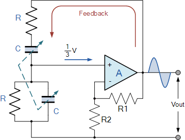
A tutorial on the Wien Bridge Oscillator circuit, which utilizes an RC phase shift oscillator to generate sine waves. The Wien Bridge Oscillator is a well-known electronic circuit used to produce sine waves. It operates based on the principle of...
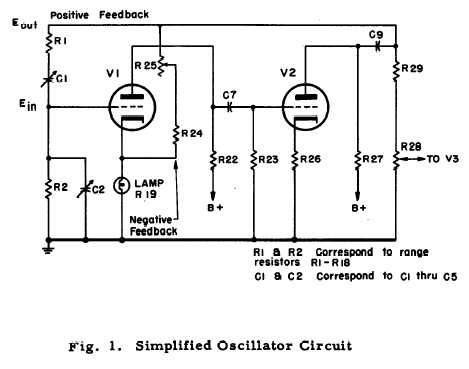
After repairing several Hewlett Packard vacuum tube voltmeters, research was conducted on the company's history. An HP-200C oscillator was located, which closely resembles the company's initial product. It is a Wien bridge resistance-tuned oscillator featuring a light bulb stabilized...
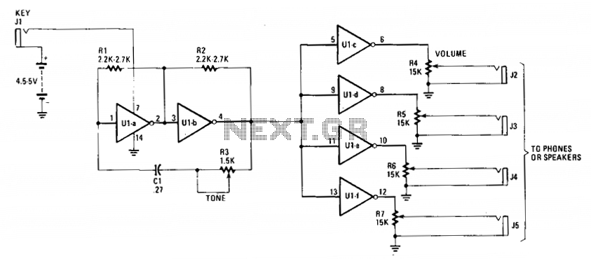
The cost-effective 7404 hex-inverter provides sufficient amplification to accommodate a broad spectrum of transducers. Engaging the switch completes the battery circuit, supplying four to five volts to the 7404. The bias for the first two inverter amplifiers (Ula and...
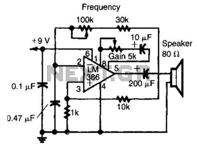
An LM386 audio power IC is configured as a feedback oscillator. It can operate with a supply voltage ranging from 6 to 12 V. The circuit is capable of driving a loudspeaker. The LM386 is a low-voltage audio power amplifier...