
CW117 CW217 CW317 12V constant-voltage charger

The 12V constant voltage charger circuit operates on the principle of maintaining a steady output voltage of 12 volts, regardless of variations in load or input voltage. The circuit typically consists of a transformer, rectifier, filter, and voltage regulator. The transformer steps down the AC voltage to a suitable level, while the rectifier converts the AC voltage to DC.
A smoothing capacitor follows the rectifier to filter out voltage ripples, providing a more stable DC output. The role of resistor R1, valued at 0.2 ohms, is crucial in limiting the charging current to prevent excessive current flow that could damage the battery or the charger itself. By increasing the internal resistance of the charger, R1 effectively slows down the charging process during the initial phase, allowing for a safer and more controlled charging environment.
The integrated voltage regulator plays a dual role in this circuit. Primarily, it ensures that the output voltage remains at a constant 12 volts, even when the input voltage fluctuates or when the load changes. Additionally, it provides overcurrent protection, which is essential for safeguarding both the charger and the connected battery. If the current exceeds a predetermined threshold, the voltage regulator will adjust its output to prevent damage, thereby enhancing the reliability and longevity of the charger.
Overall, this circuit design is essential for applications requiring a stable and reliable charging solution, such as in battery charging systems for various electronic devices. Proper selection of components, including the transformer, rectifier, and voltage regulator, along with careful consideration of resistor values, is critical for achieving optimal performance and safety in the charging process. As shown is a 12V constant voltage charger. The power supply circuit with the same basic circuit. Resistance Rl 0.2, limiting the role played, the equivalent of increasing the internal resistance of the charger can reduce the charging rate of charging the initial stage of the integrated voltage regulator plays the role of overcurrent protection.
Related Circuits

When USB power is present and the device needs to operate, VSupply is supplied directly by the USB, while a PMOS transistor isolates the battery from the supply. Resistor R3 ensures that the PMOS remains on when USB power...
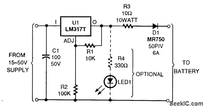
The circuit is based on an LM317T adjustable voltage regulator. The output voltage (VOUT) is defined by the formula VOUT = 1.25 (1 + R2/R1). A 10-kΩ resistor is selected for R1 and a 100-kΩ resistor for R2, allowing...
A 40-watt fluorescent tube lamp or two 20-watt tubes in series will be driven by this circuit; however, this circuit will produce less brightness than usual, since... This circuit is designed to operate a 40-watt fluorescent tube lamp or two...
The above pictured schematic diagram is just a standard constant current model with a added current limiter, consisting of Q1, R1, and R4. The moment too much current is flowing biases Q1 and drops the output voltage. The output...
The stroboscope tube requires approximately 250-400V DC for operation. This high voltage is generated by a simple voltage step-up circuit constructed from transistors Q1, Q2, and transformer T1. This circuit outputs about 230V AC, which is then rectified by...
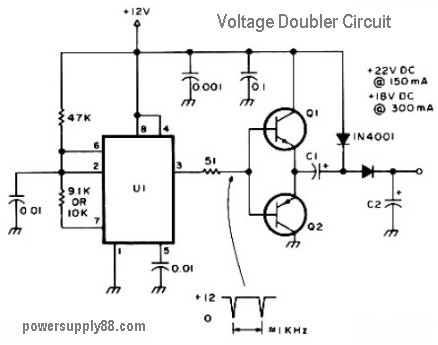
The schematic diagram originates from a 12V DC voltage doubler circuit power supply. This circuit diagram illustrates a DC voltage doubler/DC converter that transforms a 12V DC power supply into 24V DC and 18V DC outputs. It is compatible...