
Dark detector circuit using LDR LED

The dark detector circuit utilizes a photoresistor (LDR) as the primary sensing element. The LDR is a light-dependent resistor that changes its resistance based on the intensity of light falling on it. In low-light conditions, the resistance of the LDR increases significantly, allowing the circuit to detect darkness.
The circuit typically comprises a few key components: the LDR, a resistor, a transistor, and an LED or buzzer for output indication. The LDR is connected in a voltage divider configuration with a fixed resistor. As ambient light decreases, the voltage across the LDR increases, which can be fed into the base of a transistor.
When the voltage at the base of the transistor exceeds a certain threshold, the transistor turns on, allowing current to flow from the collector to the emitter. This current can then energize an output device such as an LED or a buzzer, providing a visual or audible indication of low light conditions.
To enhance the circuit's functionality, additional components such as a potentiometer may be included to adjust the sensitivity of the LDR, allowing for tuning based on the specific application or environment. Furthermore, a capacitor can be added in parallel with the output device to create a delay in response time, preventing rapid on-off cycles in fluctuating light conditions.
Overall, this dark detector circuit serves as a fundamental example of using an LDR in electronic applications, showcasing the principles of light sensing and transistor switching in a straightforward design.This is a basic dark detector/sensor circuit diagram based on a Photo Resistor (LDR) and few numbers of parts.. 🔗 External reference
Related Circuits
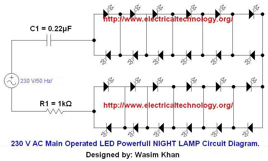
If you plan to use this circuit with a 110V 60Hz supply instead of a 230V 50Hz supply, or if you intend to modify this circuit, please refer to the section titled "Common Questions about this Circuit" found below...
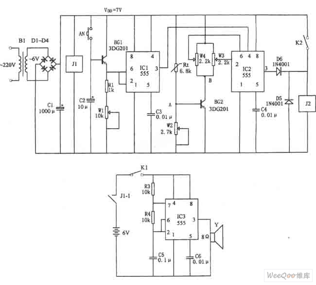
The figure illustrates the automatic watering control circuit for bean sprouts. The controller includes a step-down rectifier circuit, a power outage detection component (IC3), a timing control circuit (IC1), and a temperature control circuit (IC2). The step-down rectifier circuit...
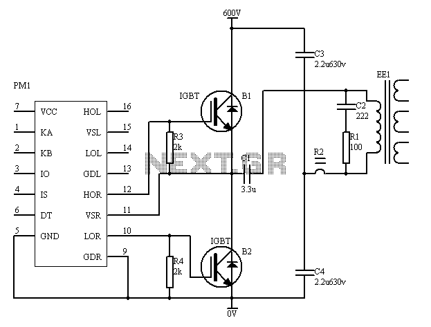
The PM4040F is utilized in switching power supply applications for medium power ranges. It is designed to drive power supplies between 200W and 800W, as illustrated in the accompanying bridge circuit. For power applications below 1000W, an alternative circuit...
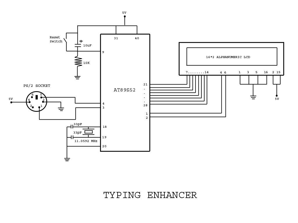
Project with Circuit and Code for a Typing Assistant using the 8051 microcontroller (AT89S52) and the PS/2 keyboard port of a computer. The project also explains the interfacing of the PS/2 port of a computer with the 8051 microcontroller. The...
It is advisable to prototype the entire circuit using a breadboard. This method simplifies the process significantly compared to attempting to determine the connections on a small printed circuit board. Prototyping a circuit on a breadboard allows for easy modifications...
The UC3842, UC3843, UC3844, and UC3845 series of oscillators can generate synchronization pulses without requiring numerous external components. The following circuit illustrates the Sync Pulse Generator Circuit Diagram for the UC3842/3/4/5. This sync pulse circuitry is capable of operating...