
Data Based IQ Modulator

The IQ_Mod project is centered around advanced modulation techniques utilizing the IQ_Mod_Setup and IQ_Mod_Data components within ADS. This project integrates several critical sub-circuits to form a comprehensive modulator design. The exclusion of the amplifier from the modulator circuit signifies a shift towards a more simplified architecture, potentially enhancing efficiency and reducing complexity in signal processing.
The sub-circuits involved include "MixerGilCel.dsn," which typically serves as the mixer stage, facilitating the combination of signals at different frequencies. The "phase_shift.dsn" sub-circuit is essential for adjusting the phase of the signals to achieve the desired modulation characteristics. The "Wilkinson.dsn" circuit often functions as a power divider or combiner, ensuring that the signals are appropriately managed throughout the modulation process.
The project encompasses multiple simulation approaches, including both circuit-level and behavioral-level analyses. The circuit-level simulations, as represented in "circuit_level_ramp.dsn" and "circuit_level_QAM.dsn," focus on the physical implementation of the modulator, allowing for detailed examination of the circuit's performance under realistic conditions. These simulations generate datasets that provide insight into the modulator's behavior, particularly in terms of amplitude variations in the I_Q waveforms.
On the other hand, the behavioral-level simulations, represented in "behavioral_level_ramp.dsn" and "behavioral_level_QAM.dsn," abstract the physical components and focus on the overall performance and characteristics of the modulation scheme. This approach enables faster simulations and can be particularly useful in the early stages of design when exploring various modulation strategies and their effects on signal integrity.
The comparison figures serve to validate the accuracy of the models employed in both simulation approaches. By juxtaposing the circuit-level and behavioral-level results, it is possible to assess how closely the models align with expected performance metrics. The strong agreement observed in the IQ trajectories and waveforms underscores the reliability of the modeling techniques applied in this project, providing confidence in the design's effectiveness for practical applications in communication systems.The IQ_Mod project illustrates the use of the IQ_Mod_Setup and IQ_Mod_Data components in ADS. These components are part of the ADS behavioral model suite found under the System - Data Models palette. "IQ_mod_ckt. dsn" is a schematic for the modulator of interest. This modulator is a modification of the circuit-level modulator constructed. The biggest difference is the removal of the amplifier ["PA_2stg. dsn"]. The modulator is constructed of the sub-circuits "MixerGilCel. dsn", "phase_shift. dsn", and "Wilkinson. dsn". "circuit_level_ramp. dsn" is a schematic for a circuit level Circuit Envelope simulation of "IQ_mod_ckt. dsn" with I_Q waveforms that have time-varying amplitude. The result is in the dataset "circuit_level_ramp. ds". "behavioral_level_ramp. dsn" is a schematic for a behavioral level Circuit Envelope simulation with I_Q waveforms that have time-varying amplitude. "IQ_mod_ckt. dsn" is modeled behaviorally with IQ_Mod_Data along with the dataset "Setup_IQ_mod_ckt. ds". The result is in the dataset "behavioral_level_ramp. ds". "circuit_level_QAM. dsn" is a schematic for a circuit level Circuit Envelope simulation of "IQ_mod_ckt. dsn" with I_Q waveforms for a 16 QAM modulation. The result is in the dataset "circuit_level_QAM. ds". "behavioral_level_QAM. dsn" is a schematic for a behavioral level Circuit Envelope simulation of with I_Q waveforms for a 16 QAM modulation.
"IQ_mod_ckt. dsn" is modeled behaviorally with IQ_Mod_Data along with the dataset "Setup_IQ_mod_ckt. ds". The result is in the dataset "behavioral_level_QAM. ds". In Figure 1, a comparison of circuit and behavioral level results is given for Circuit Envelope simulation. Both input and output waveforms are modeled accurately. In Figure 2, a comparison of circuit and behavioral level results is given for Circuit Envelope simulation.
Strong agreement is shown for both the input and output IQ-trajectories. 🔗 External reference
Related Circuits

Always use shielded LWDAQ Cable to connect the A3018 to the LWDAQ Driver, not Ethernet cables. The shielding prevents the cable from acting as a radio-frequency antenna. Proper wiring enhances data transfer immunity to static discharge. The A3018A, A3018B,...
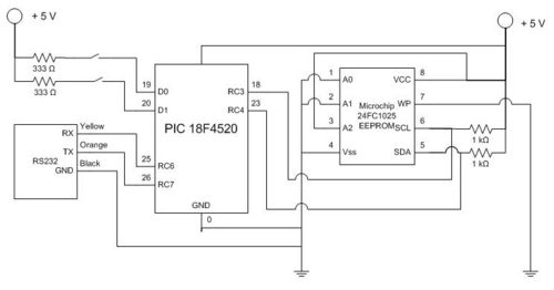
The task involves using a PIC microcontroller to log data from an analog input to an external EEPROM and subsequently sending the collected data back to a PC running MATLAB. An interrupt service routine (ISR) is utilized to read...
A simple, low component count phase locked loop that locks onto and detects the amplitude of an incoming baseband 7 bit Barker code using a switched resistor demodulator that is driven directly by a microcontroller's output pins. Balanced modulators...
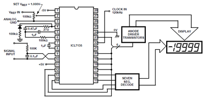
The schematic below shows the ICL7135 integrating analog-to-digital converter (ADC) functional diagram. According to the datasheet, an integrating converter is the right choice for panel meters and digital voltmeter applications. It can also be used for reducing line frequency...
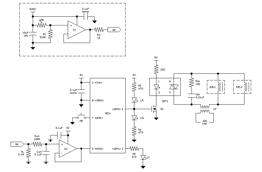
While discussing an all-linear automatic night light circuit, it was mentioned that an MCU-based Automatic Night Light Controller (ANLC) was being tested. The firmware has been tweaked since then. Recently, the sensor was installed outdoors and connected to control...

This article discusses a simple 5-channel radio remote control circuit utilizing the TX-2B and RX-2B integrated circuits from Silan Semiconductors. The TX-2B/RX-2B is a remote encoder-decoder pair suitable for remote control applications. It features five channels, a wide operating...