
DC-DC regulating converter

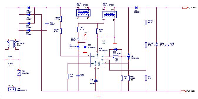
In this transformer-coupled DC-DC regulating converter, the push-pull topology is employed to effectively manage power conversion and regulation. The configuration utilizes two transistors that alternately switch on and off, allowing for efficient energy transfer from the primary winding of the transformer to the secondary winding. The SGI 524 integrated circuit plays a critical role in this design by generating the necessary PWM (Pulse Width Modulation) control signals. The oscillator frequency must be set to twice the target output frequency to compensate for the internal frequency division performed by the flip-flop within the SGI 524. This ensures that the output frequency remains stable and adheres to the design specifications.
Additionally, the current limiting feature is crucial for protecting the circuit from potential damage due to transformer saturation. In the primary side of the converter, a current sensing mechanism monitors the flow of current through the transformer. When the current exceeds a predefined threshold, the pulse width of the PWM signal is automatically reduced. This action limits the energy delivered to the transformer, preventing saturation and ensuring that the system operates within safe parameters. The combination of push-pull outputs, precise frequency control, and current limiting mechanisms contributes to the overall reliability and efficiency of the DC-DC converter circuit.Push-pull outputs are used in this transformer-coupled dc-dc regulating converter. Note that the oscillator must be set at twice the desired output frequency as the SGI 524"s internal flip-flop divides the frequency by 2 as it switches the PWM signal from one output to the other Current limiting is done here in the primary so that the pulse width will be reduced should transformer saturation occur.
Related Circuits
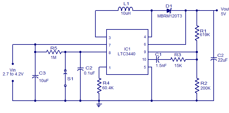
A simple 5V boost converter utilizing the LTC3440 is presented. The LTC3440 is a high-efficiency DC to DC converter capable of operating with input voltages that are below, above, or equal to the output voltage. With synchronous rectification, the...
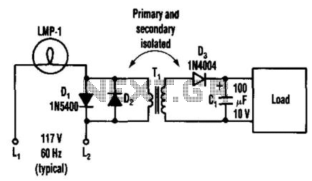
By connecting two back-to-back diodes in series with an AC power circuit, a voltage of approximately 1.4 Vpp can be achieved. This voltage is beneficial for energizing the primary coil of a small transformer. The voltage induced in the...
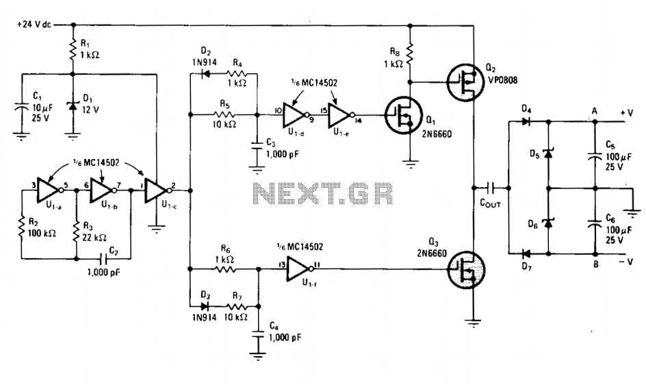
Inverters Ula and Ulb create a 20-kilohertz oscillator with a square wave output. This output is further shaped by components D2, R4, R5, D3, R6, and R7, which drive power field-effect transistors Q2 and Q3. The p-channel and n-channel...
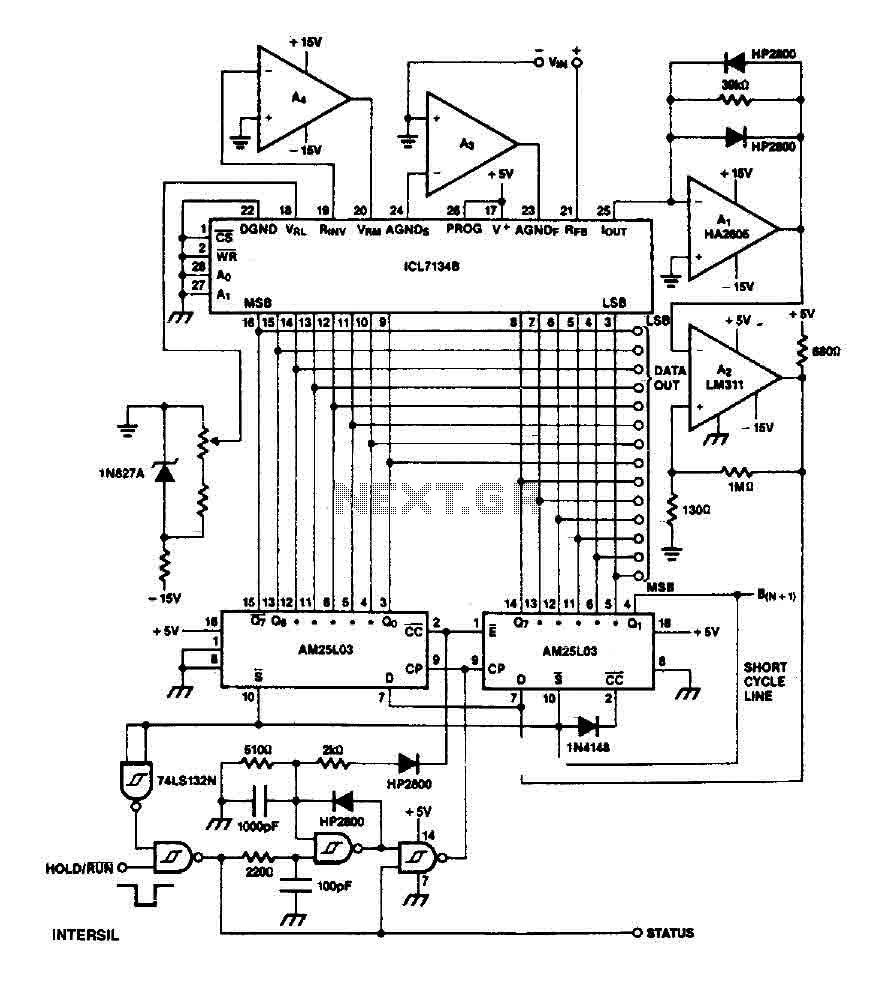
The ICL7134B circuit is a bipolar input analog-to-digital (A/D) converter that employs two AM25L03 chips to create a 14-bit successive approximation register. The comparator features a two-stage amplifier, HA2605, which is utilized to mitigate settling time issues at the...
This article outlines a proposed solution for a 200 W power supply utilizing the FSFR2100 Fairchild Power Switch (FPS). The input voltage range is 90 to 265 VRMS, and it features six outputs. The 200 W power supply circuit based...
The LT3465/LT3465A are step-up DC/DC converters designed to drive up to six LEDs in series from a Li-Ion cell. Series connection of the LEDs provides identical LED currents and eliminates the need for ballast resistors. These devices integrate the...