
DC Lessons In Electric Circuits

The design and operation of meters, particularly PMMC movements, involve several key components and principles. The core of a PMMC meter consists of a coil of wire wound around a lightweight frame, which is positioned within a permanent magnetic field. The interaction between the magnetic field created by the current in the coil and the external magnetic field generates a torque that causes the coil to rotate. This rotation is proportional to the current flowing through the coil.
The coil is typically mounted on a pivot, allowing it to move freely within the magnetic field. A spring mechanism is employed to provide a restoring force, ensuring that the coil returns to its zero position when no current is flowing. The scale on which the needle moves is calibrated to provide a direct reading of the current, voltage, or resistance being measured.
In addition to the mechanical components, modern meters often incorporate electronic circuitry that enhances their functionality. This circuitry can include analog-to-digital converters for digital displays, protection circuits to prevent damage from overcurrent, and filtering circuits to improve measurement accuracy by minimizing noise.
Calibration is an essential aspect of meter design, ensuring that the readings are accurate across the specified range of measurements. Calibration involves comparing the meter's output against known standards and making adjustments as necessary.
Overall, the evolution of meter design from mechanical to digital has significantly improved measurement accuracy and reliability, making them indispensable tools in electrical engineering and circuit analysis.A meter is any device built to accurately detect and display an electrical quantity in a form readable by a human being. Usually this "readable form" is visual: motion of a pointer on a scale, a series of lights arranged to form a "bargraph, " or some sort of display composed of numerical figures.
In the analysis and testing of circuits, there are meters designed to accurately measure the basic quantities of voltage, current, and resistance. There are many other types of meters as well, but this chapter primarily covers the design and operation of the basic three. Most modern meters are "digital" in design, meaning that their readable display is in the form of numerical digits.
Older designs of meters are mechanical in nature, using some kind of pointer device to show quantity of measurement. In either case, the principles applied in adapting a display unit to the measurement of (relatively) large quantities of voltage, current, or resistance are the same.
The display mechanism of a meter is often referred to as a movement, borrowing from its mechanical nature to move a pointer along a scale so that a measured value may be read. Though modern digital meters have no moving parts, the term "movement" may be applied to the same basic device performing the display function.
The design of digital "movements" is beyond the scope of this chapter, but mechanical meter movement designs are very understandable. Most mechanical movements are based on the principle of electromagnetism: that electric current through a conductor produces a magnetic field perpendicular to the axis of electron flow.
The greater the electric current, the stronger the magnetic field produced. If the magnetic field formed by the conductor is allowed to interact with another magnetic field, a physical force will be generated between the two sources of fields. If one of these sources is free to move with respect to the other, it will do so as current is conducted through the wire, the motion (usually against the resistance of a spring) being proportional to strength of current.
The first meter movements built were known as galvanometers, and were usually designed with maximum sensitivity in mind. A very simple galvanometer may be made from a magnetized needle (such as the needle from a magnetic compass) suspended from a string, and positioned within a coil of wire.
Current through the wire coil will produce a magnetic field which will deflect the needle from pointing in the direction of earth`s magnetic field. An antique string galvanometer is shown in the following photograph: Such instruments were useful in their time, but have little place in the modern world except as proof-of-concept and elementary experimental devices.
They are highly susceptible to motion of any kind, and to any disturbances in the natural magnetic field of the earth. Now, the term "galvanometer" usually refers to any design of electromagnetic meter movement built for exceptional sensitivity, and not necessarily a crude device such as that shown in the photograph.
Practical electromagnetic meter movements can be made now where a pivoting wire coil is suspended in a strong magnetic field, shielded from the majority of outside influences. Such an instrument design is generally known as a permanent-magnet, moving coil, or PMMC movement: In the picture above, the meter movement "needle" is shown pointing somewhere around 35 percent of full-scale, zero being full to the left of the arc and full-scale being completely to the right of the arc.
An increase in measured current will drive the needle to point further to the right and a decrease will cause the needle to drop back downof metal connection terminals on the back for current f the scale sweep insteype of meter or size of meter movement, there we`ll need to design a 🔗 External reference
Related Circuits
This magic lamp appears to be an ordinary frosted light bulb with a rather unusual characteristic. Whenever a finger touches the base threads and center contact, the lamp magically lights up without wires. It creates a compelling illusion if...
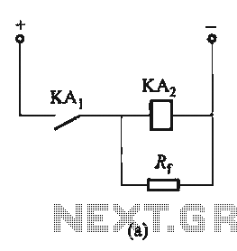
The circuit depicted in Figure 6-24 includes a relay coil with both ends connected in parallel to either a resistor Rf or an auxiliary diode VD. This configuration is equivalent to providing power after a short circuit, which increases...
There are a number of ways to obtain the low voltages required to run small projects from the wall power outlet. The simplest way is to buy a factory-built molded supply which is designed to plug directly into the...
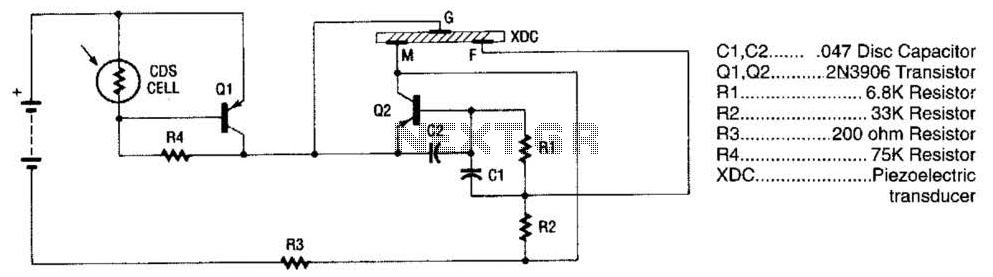
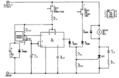
The alarm utilizes a fixed-frequency piezoelectric buzzer alongside a cadmium-sulfide (CDS) cell and a two-transistor circuit to create a distinctive effect. When light reaches the CDS photoelectric cell, the alarm remains silent. However, in the absence of light, transistor...
The purpose of this timer is to disconnect the compressor circuit and connect a resistive heating element located near the evaporator at regular time intervals. The defrost heater is controlled by a thermostat and is used to melt any...
The circuit presented is a standard Colpitts oscillator, commonly utilized in many amateur radio homebrew transmitters. This specific circuit is designed to operate effectively within a frequency range of 1500 kHz to 8000 kHz. To accommodate lower frequencies, it...