
DC Motor Control circuit

The schematic design integrates various electronic components to facilitate the intended functionality. The core of the circuit is based on a PIC microcontroller, which serves as the central processing unit. The connections to the microcontroller are critical, as they determine how the device interacts with other components in the circuit.
The use of a 220k resistor is specified, which plays a crucial role in setting the appropriate current levels within the circuit. If a 220k resistor is not available, selecting a higher resistance value is advisable to ensure that the circuit operates within safe parameters. This approach will help prevent excessive current flow that could potentially damage sensitive components.
The circuit layout is designed to be compatible with the Olimex P-40 Development board, which provides a convenient platform for prototyping and testing. The development board typically includes additional features such as power supply regulation and I/O pin access, making it easier to implement the schematic without needing extensive modifications.
It is essential to ensure that the software programmed into the PIC microcontroller aligns with the intended operation of the circuit. The preprogrammed software must be loaded onto the microcontroller before testing the schematic to confirm that it functions as expected.
In summary, the schematic effectively demonstrates the integration of essential electronic components, emphasizing the importance of precise resistor values and the compatibility with development boards for successful implementation. Proper attention to these details will facilitate a successful experiment and ensure reliable functionality.The schematic seen below uses all the hardware components we`ve seen up to this point. If you`re following along with this tutorial be sure to follow it exactly as seen below. If you don`t have 220k resistor use the closest value you can find near it, preferrably higher. Components are labeled to the best of my ability. Parts hooked up to the PIC are minial and it should be recognized that this experiment actually uses the Olimex P-40 Development board and not a bare bones PIC layout as seen in the schematic. However if you choose to follow the schematic exactly it will work the same as it would with the development board, provided of course that the software is preprogrammed onto the PIC.
🔗 External reference
Related Circuits
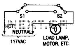
This switching arrangement is utilized in both domestic and industrial environments to enable control of a light or other AC-operated device from multiple locations. This switching arrangement, commonly referred to as a multi-way switching system, is designed to facilitate the...
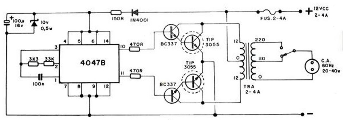
The converter transforms 12 VDC to 220 VAC, allowing for the conversion of 12 volts DC into 220 volts AC. The circuit diagram provided illustrates a simple converter circuit. This DC to AC converter can supply voltage for a...
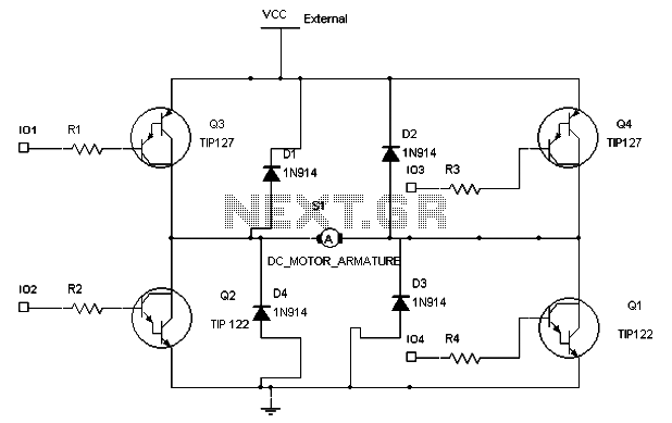
To maintain a constant speed of the motor under varying load conditions, a control application circuit is required. An H-Bridge circuit can be utilized to manage both the speed and direction of the motor. The accompanying diagram illustrates the...

One electronic ballast circuit is depicted in Figure 2-11. This circuit utilizes a specialized fluorescent lamp starter thyristor, SCR Y1112, which is superior to ordinary thyristors due to its ability to maintain a higher current value and dU/dt values....
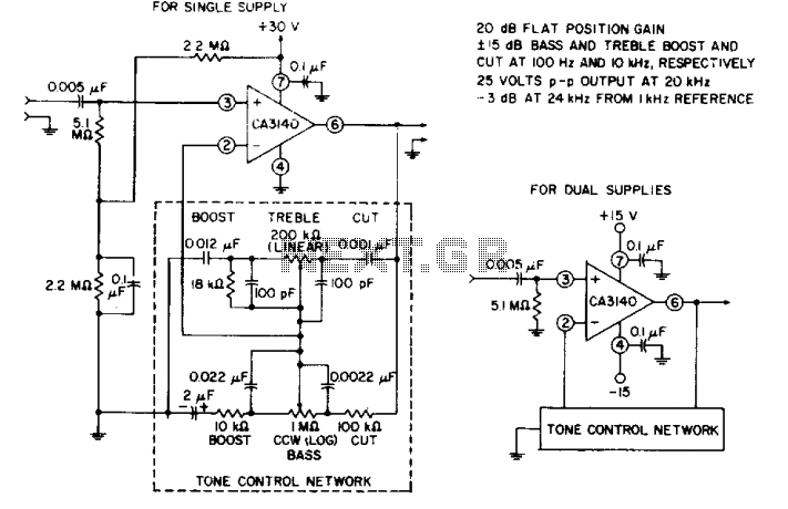
The circuit effectively utilizes the high slew rate, wide bandwidth, high input impedance, and high output voltage capability of the CA3140 BiMOS operational amplifier. The wideband gain of this circuit is equal to the ultimate boost or cut plus...

This document details a 2W audio power amplifier circuit that utilizes a 14-pin LM380 package as the amplification element. The input signal is managed by a volume control potentiometer (Rp) rated at 20k ohms, with a coupling capacitance of...