
DC motor controller diagram with SCR and cmos ic

The speed motor controller circuit for a 12V DC motor typically includes several key components that work together to regulate the motor's speed. The circuit may consist of a variable resistor (potentiometer), a transistor or MOSFET for switching, a diode for flyback protection, and a microcontroller or timer IC for precise control.
The potentiometer allows the user to set the desired speed by varying the resistance in the circuit, which in turn adjusts the voltage supplied to the motor. The transistor or MOSFET acts as a switch that controls the power delivered to the motor based on the input from the potentiometer. This switching action can be implemented using Pulse Width Modulation (PWM) to efficiently control the speed without wasting energy.
The diode placed in parallel with the motor serves as a flyback diode, protecting the circuit from voltage spikes generated when the motor is turned off. This is crucial for maintaining the longevity and reliability of the components.
For precise speed control, a microcontroller or timer IC can be integrated into the circuit. This allows for more advanced features such as speed feedback, acceleration profiles, and the ability to set maximum speed limits. The output from the microcontroller can modulate the duty cycle of the PWM signal, providing a smooth and responsive control over the motor's speed.
Overall, this speed motor controller circuit is designed to provide efficient and adjustable control over the operation of a 12V DC motor, making it suitable for various applications where precise speed regulation is necessary.This is speed motor controller circuit of 12V DC motor. You can adjust the speed of rotation of the spindle motor from 5-60 cycles per minute. The work of.. 🔗 External reference
Related Circuits
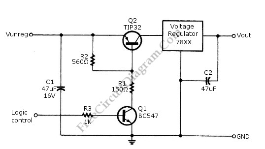
Logic power control of an analog regulator can be useful in applications where a digital circuit or controller needs to manage a power source, such as in EEPROM programmers or other power control systems. This circuit provides ON-OFF control...
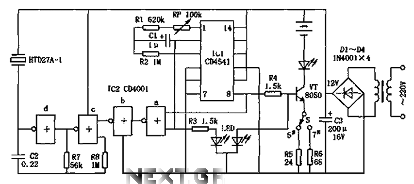
The CD4001/CD4541 nickel-cadmium battery automatic charger circuit is illustrated in the figure. This circuit is designed for charging up to seven rechargeable nickel-cadmium batteries. It features automatic charging with constant current characteristics. Once powered, the circuit activates an internal...
There are various configurations for crystal oscillators, with the most common being discrete and integrated circuits like the Pierce and RLC Bridge. The discrete Pierce oscillator is a suitable choice when good frequency stability and a relatively simple circuit...
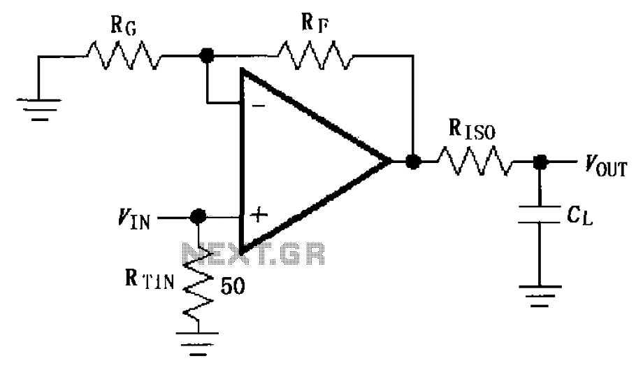
The circuit depicted in FIG demonstrates the MAX4450/4451 utilizing a capacitive load drive circuit with an isolation resistor (RISO). This configuration is situated between the output terminals and the load, along with an additional resistor, to mitigate overshoot and...
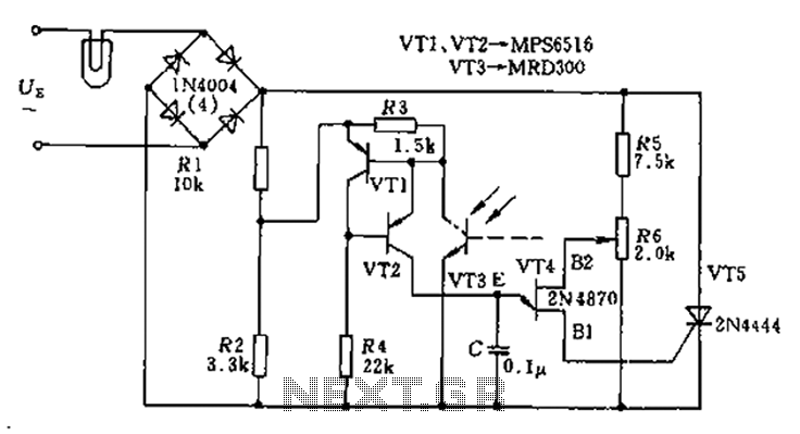
The circuit utilizes a thyristor-based AC automatic voltage regulator to stabilize the brightness of lamp L. A diagonal line connects the thyristor to the T5 bridge. The trigger pulse for the thyristor is generated by a single-junction transistor, VT4....
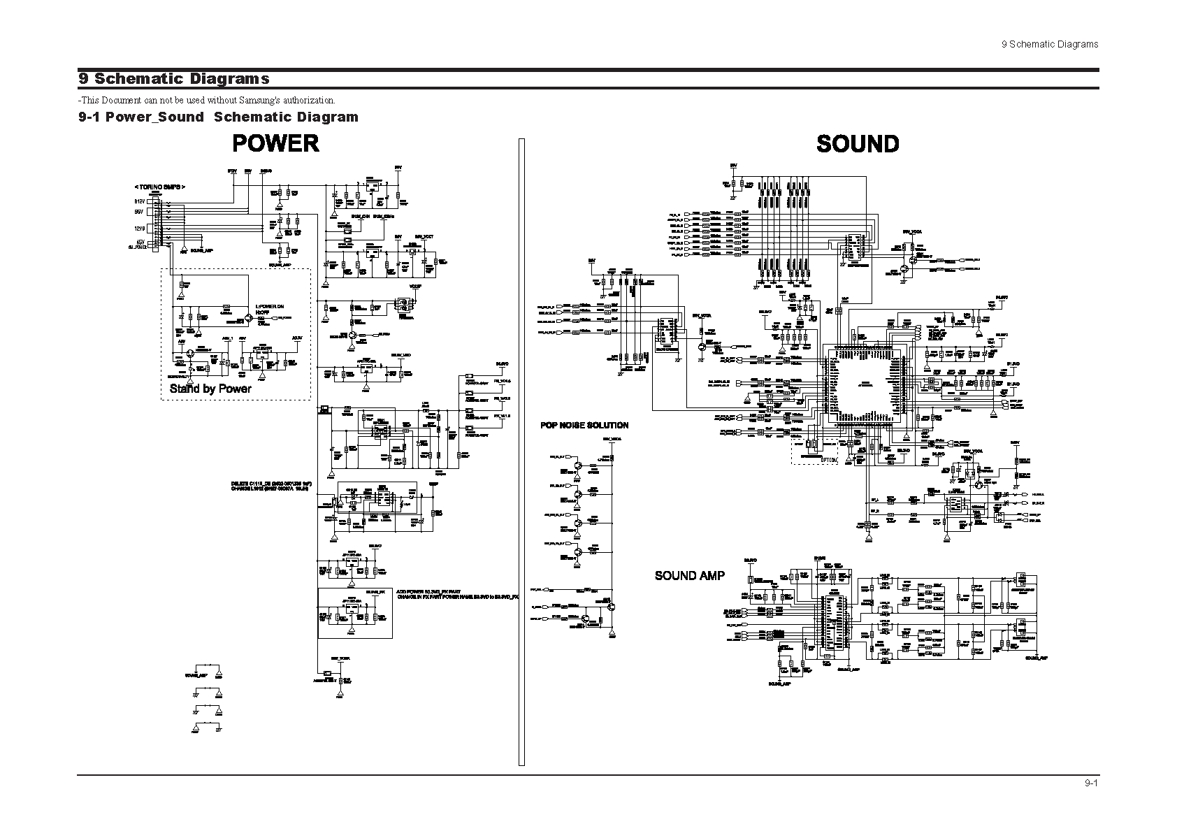
Samsung C3330 Circuit Diagram Download Manual PDF Download. The Samsung C3330 circuit diagram serves as a comprehensive reference for understanding the electronic architecture of the device. This schematic provides detailed insights into the interconnections between various components, including the microcontroller,...