
DC motor driver circuit design using LM628 LM629 dedicated motion-control processors

The circuit utilizes the LM628 and LM629 processors, which are specifically designed for motion control applications, making them suitable for managing both DC and brushless DC servo motors. The integration of the LM12 high-power operational amplifier within the motor driver circuit allows for efficient control of motor functions, providing the necessary power handling capabilities.
In the schematic, the gain-setting resistors R1 and R2 play a critical role in determining the overall gain of the amplifier circuit. By carefully selecting their values, the desired amplification can be achieved while ensuring that the output remains within the limits of the power supply. The specified gain of 2.2 is optimal for maintaining linearity in the output, particularly under conditions that approach saturation. This is crucial because exceeding the linear range can lead to distortion and inefficiencies in motor control.
The power supply configuration of ±30V is essential for achieving the required output levels, allowing the circuit to deliver ±22V at the output. This voltage range is particularly advantageous for applications requiring high torque and precise control over the motor's performance. The non-linear characteristics of the amplifier when saturated necessitate careful design considerations to ensure that the system remains stable and responsive during operation.
Overall, this motor driver circuit, leveraging the capabilities of the LM628, LM629, and LM12, presents a robust solution for various servomechanism applications, facilitating effective control of DC and brushless DC motors with high precision and reliability.Using the LM628 LM629 dedicated motion-control processors can be designed a variety of DC and brushless DC servo motors, and other servomechanisms applications. The power path of this electronic project, motor driver is based on the LM12 high power operational amplifier that can be used in some other power applications like : motor controller,
audio amplifiers or some other power applications. Resistors R1 and R2 should be chosen to set the gain to provide maximum output voltage consistent with maximum input voltage. This circuit provides a gain of 2. 2, which allows for amplifier output saturation at ±22V with a ±10V input, assuming power supply voltages of ±30V.
The amplifier gain should not be higher than necessary because the system is non-linear when saturated, and because gain should be controlled by the LM628. 🔗 External reference
Related Circuits
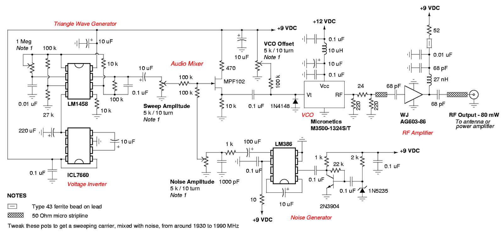
An admirable DIY GSM jammer or cellular mobile phone jammer schematic diagram designed for use with GSM1900, operating within the frequency range of 1930 MHz to 1990 MHz. The GSM1900 cellular mobile phone system is utilized in the USA,...
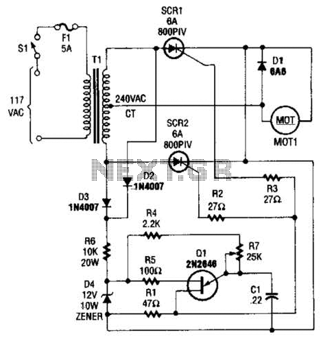
The speed-control switch provides effective control and stability across its entire operating range. This circuit utilizes two SCR devices arranged in a full-wave configuration to manage the DC power supplied to a motor. A center-tapped transformer is employed to...
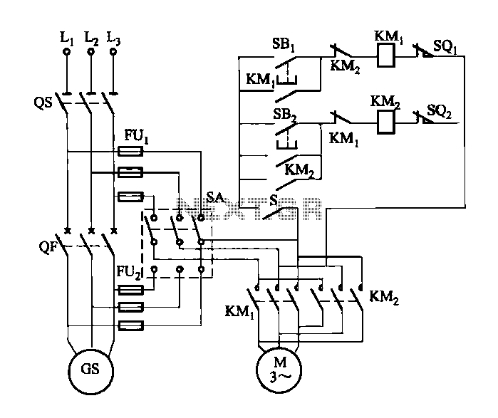
FIG M is a variable speed motor control for the opening and closing of a wicket gate. It features an electric governor. The system is activated by a power switch (SA) located on the front grid, and a toggle...
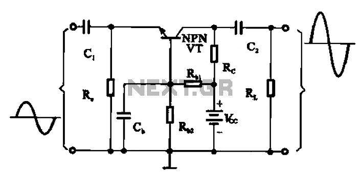
A common base transistor amplifier circuit is characterized by its basic structure, which includes key components such as a biasing resistor, capacitors for coupling, and an amplifying transistor. The circuit features four resistors that establish the quiescent point, with...
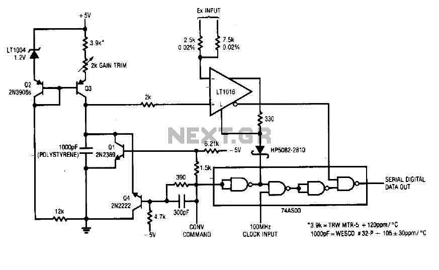
Each time a pulse is applied to the control input for conversion, Q1 resets the 1000 pF capacitor to 0 V. This resetting action takes 200 ns, after which the capacitor begins to charge linearly. In precisely 10 microseconds,...
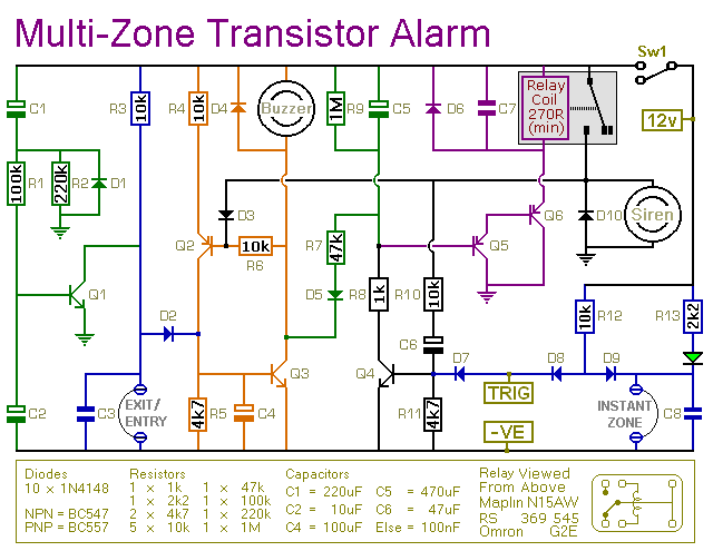
This transistor-based alarm features automatic exit and entry delays, along with a timed bell cut-off and system reset. In addition to the exit/entry zone, the basic alarm board includes one instant zone, which is sufficient for many applications. However,...