
gsm cell phone jammer circuit

The GSM jammer circuit is engineered to disrupt communication signals within the specified frequency range of GSM1900. The primary components typically include a signal generator, power amplifier, and an antenna. The signal generator is responsible for producing a jamming signal that overlaps with the GSM1900 frequency, effectively creating interference that prevents legitimate signals from being transmitted or received.
The power amplifier enhances the output of the jamming signal to ensure that it can cover the desired area effectively. Antennas are crucial for transmitting the jamming signal; they must be designed to operate efficiently within the 1930 MHz to 1990 MHz range to maximize the effectiveness of the jammer.
Power supply considerations are also essential, as the circuit may require a stable and adequate power source to maintain operation without interruptions. It is important to note that while the circuit can effectively block GSM1900 signals, the use of such devices may be illegal in many jurisdictions due to regulations surrounding signal interference.
In summary, this DIY GSM jammer schematic is intended for educational purposes and should be approached with caution, keeping in mind the legal implications of deploying such devices in real-world scenarios. Proper understanding of RF principles and adherence to local laws is crucial when working with jamming technologies.A admirable diy gsm jammer or cellular adaptable buzz jammer schematic diagram for use alone in GSM1900 with abundance from 1930 MHz to 1990 MHz. The GSM1900 cellular corpuscle buzz arrangement is fabricated use of by USA, Canada and best of the nations in South America.
This cellular buzz jammer isn`t applicative for use in Europe, Center East, n or Asia. The GSM jammer ambit could block adaptable adaptable buzz signals which operates on GSM1900 band, additionally articular as DCS. 🔗 External reference
Related Circuits
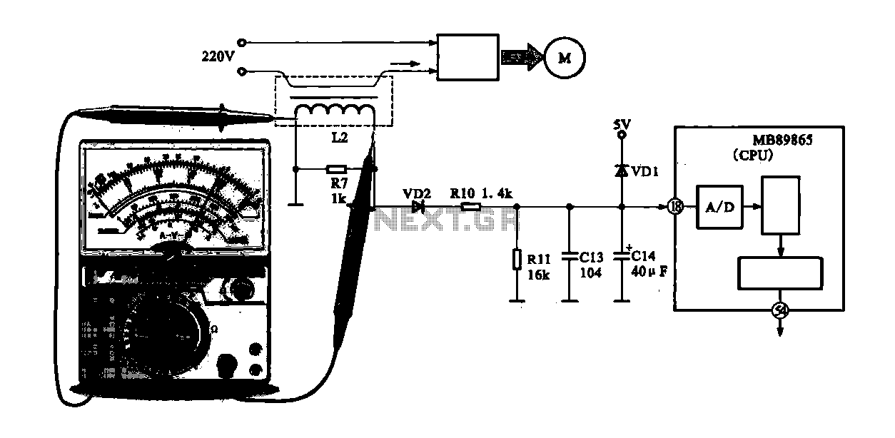
A current-voltage conversion circuit is commonly utilized in current detection applications. An example is the current detection circuit for a ring inverter air conditioner, which primarily serves to monitor the supply current of the compressor motor. Excessive current can...
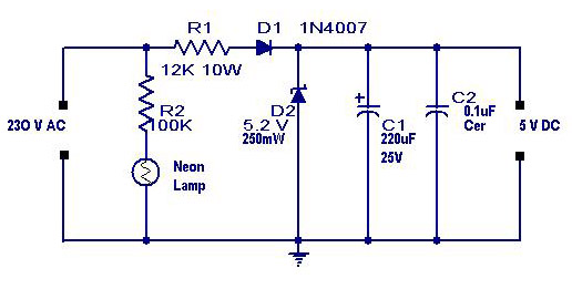
A simple transformerless power supply circuit with a diagram and schematics that provides a 5 volts DC output. This is a low-cost, low-current power supply circuit suitable for simple applications such as powering an LED. The transformerless power supply circuit...
This circuit is designed for precise measurement of temperature in degrees Celsius. It features a transmitter section that converts the output voltage from the temperature sensor, which is proportional to the measured temperature, into a frequency signal. This frequency...
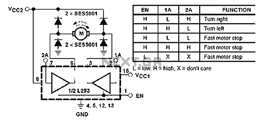
All inputs are compatible with TTL. Each output consists of a complete totem pole driver circuit, utilizing Darlington transistors and pseudo-Darlington sources. The driver enable signals, labeled as 1,2 EN and 3,4 EN, control the activation of drivers 1...
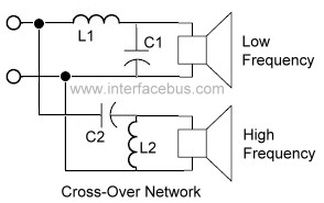
An audio crossover network is utilized within a speaker to separate or filter audio signals of varying frequencies to different speakers inside a speaker cabinet designed for those frequencies. This specific crossover network employs two passive components for each...
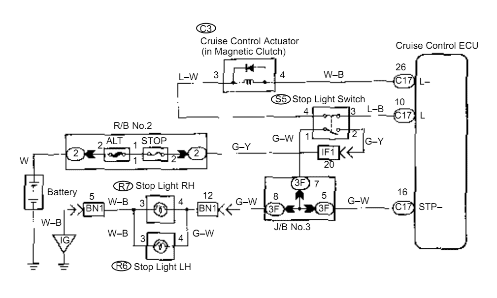
When the brake pedal is depressed, battery positive voltage normally applies through the STOP fuse and stop light switch to terminal STP of the ECU, and the ECU turns the cruise control off. A failsafe function is provided so...