
DC motor servo control circuit diagram

The described circuit operates as a position control system for a motor, utilizing a feedback mechanism to achieve precise positioning. The input DC voltages, denoted as E and O, are applied to the motor driver circuit, which translates these voltages into corresponding motor movements. The motor is designed to respond to the input voltages by adjusting its position along a defined range.
The position feedback is provided by a potentiometer, which is mechanically linked to the motor's shaft. This potentiometer has a resistance of 1k ohms and functions as a voltage divider. As the motor rotates, the wiper of the potentiometer moves along the resistive track, generating a voltage that is proportional to the motor's position. This feedback voltage is then compared to the input voltage using a differential amplifier.
The differential amplifier plays a crucial role in determining the operational state of the motor. When the voltage from the potentiometer wiper matches the input voltage (E or O), the output of the differential amplifier becomes zero. This condition indicates that the motor has reached the desired position and should remain stationary. Conversely, if the input voltage differs from the feedback voltage, the differential amplifier produces a non-zero output, prompting the motor to either move forward or reverse, depending on the polarity and magnitude of the signal.
This feedback control system ensures that the motor can accurately position itself in response to varying input voltages, allowing for precise control in applications such as robotics, automation, or any system requiring accurate positioning. Proper tuning of the circuit components, such as the potentiometer value and the gain of the differential amplifier, is essential for optimal performance and stability of the motor control system.In the circuit, when E, O are input DC voltage, the motor will be moved to a position corresponding with the voltage. The potentiometer connected to the same coaxially of motor is used as position feedback. When the given voltage is equal to 1k potentiometer wiper contact voltage, the differential amplifier output is zero, so the motor is stationary; Otherwise, the motor will be transferred or reversal according to the size of the signal.
🔗 External reference
Related Circuits

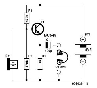
The circuit employs a field-effect transistor (FET) at the input of a Schmitt trigger, allowing the use of a low-value capacitor. The trigger, controlled by Q1 and O2, exhibits a hysteresis of approximately 3V, regulated by a 3V zener...
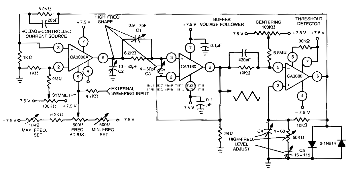
This function generator features an adjustment range exceeding 1,000,000 to 1 and utilizes a CA3160 BiMOS operational amplifier as a voltage follower. It incorporates a CA3080 operational transconductance amplifier (OTA) as a high-speed comparator, alongside another CA3080 configured as...
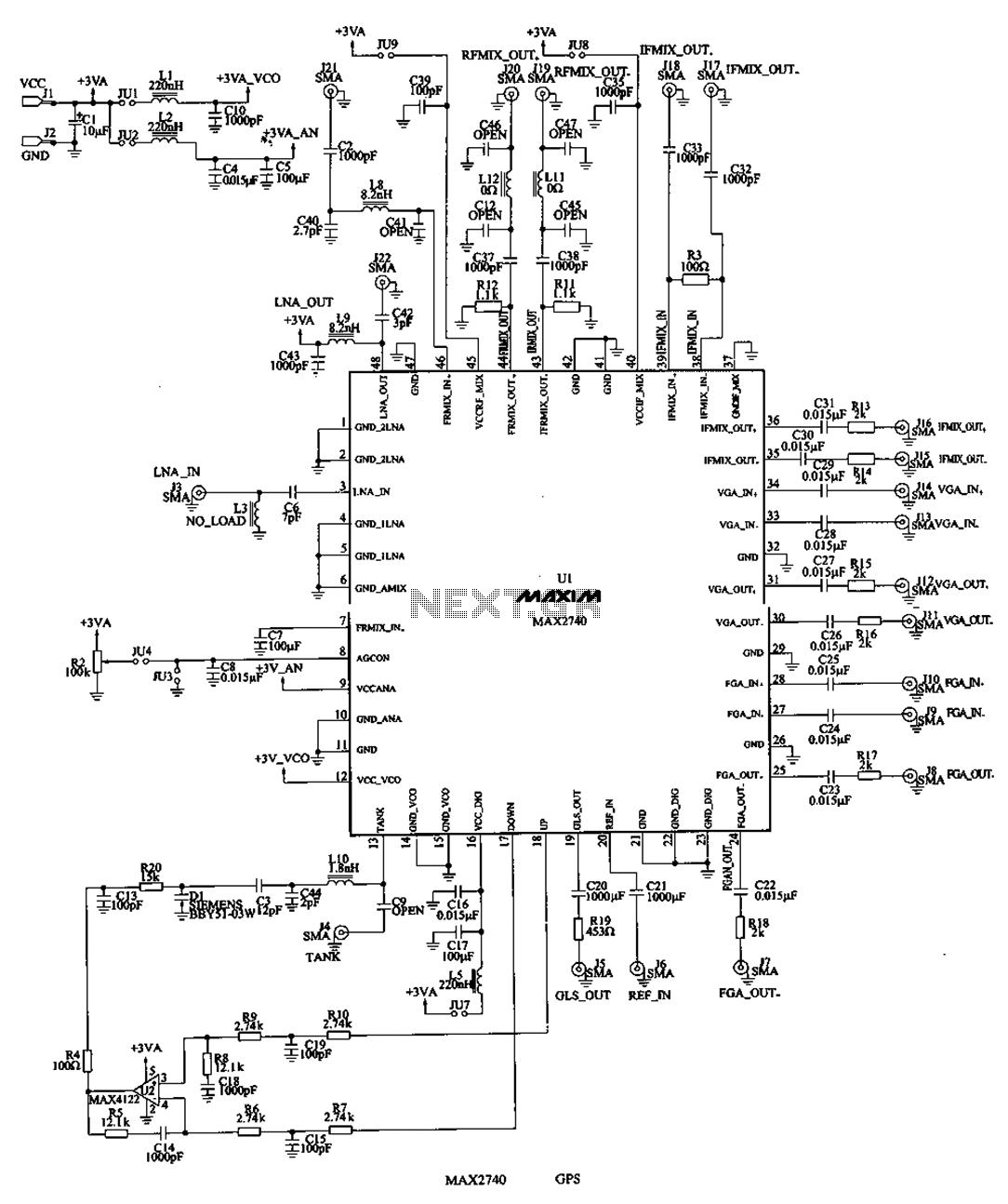
The MAX2740 is a complete GPS receiver down converter chip that processes the signal from the antenna to the input of digital signal processing. The receiver channel of the MAX2740 includes a low-noise amplifier (LNA), a downconverter, a variable...
The metronome circuit has been assembled multiple times without success. Two manufacturers of the 555 timer, ON Semiconductor and National Semiconductor, provide circuit designs that differ from the original. In their designs, pins 2, 6, and 7 are not...
This circuit is capable of automatically charging 6V and 12V batteries quickly and accurately. A key factor in the successful operation of the circuit is the use of a high-quality transformer (T1) that features excellent insulation and short-circuit resistance. The...
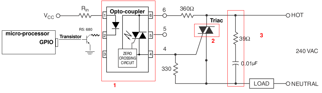
A light-dimming control system is being developed for a 240V heat lamp with a power dissipation of approximately 250W. The objective is to adjust the heat output of the lamp using control from a microprocessor. The development is based...