
IN8510 and power motor driver circuit composed of DAC7520
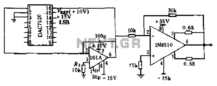
The described circuit utilizes the BTS412B and BU271L components to create a robust and efficient H-bridge configuration suitable for driving DC motors in automatic door systems. The H-bridge topology allows for bidirectional control of the motor, enabling it to open and close the doors as required. The high-side switches, represented by the BTS412B, are responsible for connecting the motor to the positive supply voltage, while the low-side switches, represented by the BU271L, connect the motor to ground.
The integration of CMOS logic levels for controlling the four switches ensures compatibility with modern digital control systems, allowing for precise and efficient operation. The logical drive outputs from the BTS412B can be used to control additional components or provide feedback to a microcontroller, enhancing the system's functionality. The inclusion of an LED for fault indication is a critical feature, providing immediate visual feedback regarding the operational status of the circuit.
The 12kΩ resistance at the left leg midpoint when the switches are off acts as a safeguard against false open load detection by the BTS412B. This design consideration is essential for maintaining the reliability of the system, as it prevents unnecessary fault signals from being triggered during normal operation. The ability of the right BTS412B to detect actual open load conditions further enhances the circuit's fault tolerance, ensuring that any issues can be promptly identified and addressed.
Overall, this H-bridge motor drive circuit is well-suited for applications requiring reliable and efficient control of DC motors, particularly in automatic door mechanisms where safety and performance are paramount.BTS412B as two high-side power MOSFET switch and two BU271L 50v for the low-side switch, can be composed of bi-directional H-bridge DC motor drive circuit shown in Figure 11-1l. The circuit is an electrical automatic doors design, continuous current up to 6A. Four-leg switches are directly controlled by CMOS logic levels. Two BTS412B state output of the logical drive or a transistor, the LED displays the fault status. Left leg midpoint -to-ground resistance when 12ktl four H-bridge switches are turned off, will not be BTS412B mistaken Open load. Once open load occurs, the right of BTS412B can detect it and issue a fault signal.
Related Circuits
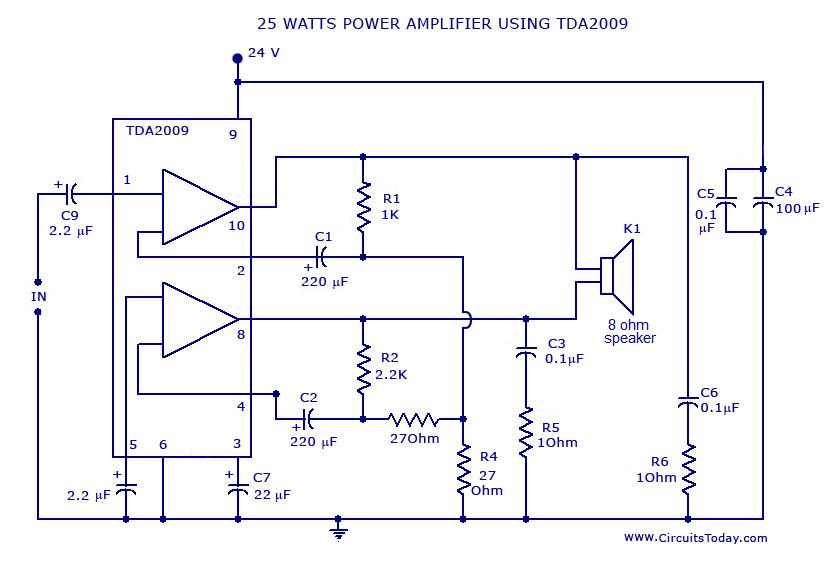
Power amplifier circuit diagram with schematics. This simple audio power amplifier circuit is designed for 25 watts output power using TDA 2009 IC, which has two channels (stereo), 12.5 W for each channel. The described power amplifier circuit utilizes the...
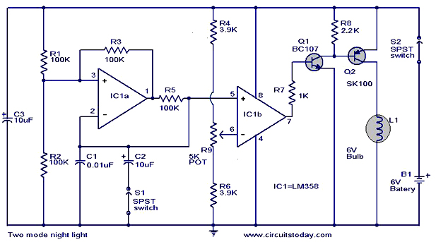
The operation and circuit diagram of a two-mode night light circuit are provided below. The two-mode night light circuit is designed to operate in two distinct lighting modes, typically offering a choice between a standard brightness setting and a dimmer,...
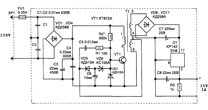
The pulse transformer T1 utilizes a ferrite core, specifically M2500NMS-2 or M2000NM9, with dimensions of Sh5h5 (cross-section of the magnetic coils at 5G—5 mm with a center gap). The winding wire is of type PEL-2. The primary winding consists...
This little guide for every electronics tester would actually have to lie in the toolbox. You can have components such as resistors, capacitors, diodes, etc. of testing. T1 and T2 form a Darlington. Therefore only need a small base...

A Field Effect Transistor (FET) is an amplifying device where the output current is influenced by the input voltage. The FET preamplifier described here is sensitive. The Field Effect Transistor (FET) operates by utilizing an electric field to control the...
It was observed that balls were becoming lodged in the ball trough, failing to load into an upkicker or not resting correctly on the trough ball microswitches or optos, which caused the machine to register a missing ball. Initially,...