
dc servo motor controller

The A3952S integrated circuit is a versatile solution for motor control applications, particularly in the context of DC servo motors. This IC integrates several functions that simplify the design of motor driver circuits. The primary features of the A3952S include its ability to handle continuous output currents up to 2 A and operate within a voltage range of 8 V to 50 V, making it suitable for a wide array of applications.
In the schematic for the DC servo motor driver, the A3952S is connected to the motor, power supply, and various passive components. The circuit typically includes resistors and capacitors for filtering and stability, ensuring that the motor operates smoothly without unwanted oscillations. The PHASE terminal is crucial for controlling the direction of the motor. By toggling this terminal, the user can reverse the motor's direction, which is essential for applications requiring bidirectional motion.
In addition to direction control, the A3952S provides features such as current sensing and thermal shutdown, which enhance the reliability of the motor driver circuit. The back EMF generated during abrupt direction changes necessitates careful consideration of the circuit design to prevent damage to the components. The design must accommodate the transient currents that occur, especially when switching directions, to ensure the longevity of the integrated circuit and the motor.
Overall, the A3952S offers a compact and efficient solution for controlling DC servo motors, making it an excellent choice for hobbyists and professionals alike in various electronic projects.As we presented in another article the A3952S integrated circuit ( designed by Allegro MicroSystems ) can be used to design very simple and useful motor driver circuits. In the precedent article was presented a simple bipolar stepper motor driver circuit that use two A3952S circuits.
As we presented in that article, the A3952S is capable of cont inuous output currents up to 2 A and operating voltages range up to 50 V. This circuit presents a simple DC servo motor application that can be used in various electronic projects. As you can see in the circuit schematic this Dc servo motor driver schematic circuit use just one integrated circuit and other few external electronic components.
With bidirectional dc servo motors, the PHASE terminal can be used for mechanical direction control. Similar to when braking the motor dynamically, abrupt changes in the direction of a rotating motor produce a current generated by the back EMF. The current generated will depend on the mode of operation. 🔗 External reference
Related Circuits
To build a stepper motor tester, the circuit includes two sets of drivers that support both unipolar and bipolar stepper motors. The control circuit and driver circuit are powered by separate supplies, allowing compatibility with a wider range of...
This circuit can control a small DC motor, like the one in a tape recorder. When both the points A and B are "HIGH," Q1 and Q2 are in saturation. Hence, the bases of Q3 to Q6 are grounded....
This is my long history the device that controls my home's night light, air-conditioner, etc. The device is a Miniature Real-time Controller. The circuit uses only three chips, a 89C2051, DS275 (or MAX232), and 74LS07 open collector driver. The...
Stepper motors are a recurring subject. This circuit converts a clock signal from a square wave generator into signals with a 90-degree phase shift. Stepper motors are widely used in applications requiring precise control of angular position, speed, and acceleration....
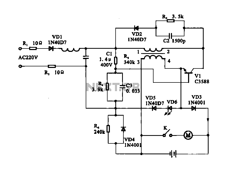
Electric shaver motor drive circuit. It illustrates a typical motor drive circuit for an electric shaver. AC 220V is used to charge the battery through the charging circuit, which also provides power to the motor. After activating the charge-on...
This circuit is 12 volt motors and lights well regulated. The scheme operates with PWM (Pulse Width Modulation). By IC1, a 555 is a square wave generated by a controllable duty cycle. This means that the width of the...