
DC to AC inverter

This DC-to-AC inverter circuit utilizes a 555 timer IC configured as a low-frequency oscillator to generate a square wave signal. The frequency of oscillation is adjustable between 50 Hz and 60 Hz using a potentiometer (R4), allowing for compatibility with standard AC line frequencies. The output from the 555 timer is fed into a pair of transistors (Q1 and Q2) configured in a push-pull arrangement. These transistors amplify the square wave signal to drive the primary winding of a transformer (T1), which is a filament transformer connected in reverse to achieve the necessary step-up in voltage.
The transformer plays a crucial role in converting the low-voltage square wave signal into a higher voltage AC output. The output waveform is further refined by the combination of capacitor C4 and inductor L1, which serve as a low-pass filter to smooth the output, approximating a sine wave shape. This filtering is essential for reducing harmonics and providing a cleaner AC output suitable for powering AC devices.
The circuit can accommodate input voltages ranging from +5V to +15V DC, making it versatile for various applications. The capacitance value of the 2700uF capacitor should be selected based on the working voltage to ensure reliability and safety. The choice of transistors Q1 and Q2 is flexible, with recommended replacements including TIP41B, TIP41C, NTE196, and ECG196 for the NPN transistor (Q1), and TIP42B, TIP42C, NTE197, and ECG197 for the PNP transistor (Q2). It is important to ensure that the transistors are correctly oriented and functioning properly, as well as confirming that the filament transformer is connected in the correct polarity.
In troubleshooting, if the inverter does not operate as expected, several checks should be performed. These include verifying the reverse connection of the filament transformer, measuring the voltage after L1, ensuring that the ground reference is established correctly, and confirming the functionality of the 555 timer by checking for a pulse at pin 3. Additionally, the integrity of the transistors should be verified to rule out any defects. Proper assembly and component selection are essential for the successful operation of this inverter circuit.This DC-to-AC inverter schematic produces an AC output at line frequency and voltage. The 555 is configured as a low-frequency oscillator, tunable over the frequency range of 50 to 60 Hz by Frequency potentiometer R4. The 555 feeds its output (amplified by Q1 and Q2) to the input of transformer T1, a reverse-connected filament transformer with the necessary step-up turns ratio.
Capacitor C4 and coil L1 filter the input to T1, assuring that it is effectively a sine wave. Adjust the value of T1 to your voltage. The output (in watts) is up to you by selecting different components. Input voltage is anywhere from +5V to +15Volt DC, adjust the 2700uF cap's working voltage accordingly. Replacement types for Q1 are: TIP41B, TIP41C, NTE196, ECG196, etc. Replacement types for Q2 are: TIP42B, TIP42C, NTE197, ECG197, etc. Don't be afraid to use another type of similar specs, it's only a transistor. If the whole thing is working, good. If not, relax and don't get frustrated. Do the following checks: 1) You have connected the filament transformer in REVERSE yes? 2) If not, disconnect the power and reverse. If you have, disconnect the transformer and measure the voltage after L1 and ground. 3) Just in case, GROUND for this circuit is same as negative (-). 4) Q1/Q2 are oposites, e.i. npn/pnp. 5) Is your 555 perhaps defective? Disconnect R3 from pin 3 and check pin 3 for a pulse. 6) Check your transistors to make sure they are not defective. 🔗 External reference
Related Circuits
This circuit diagram for a 12V inverter is straightforward to construct, utilizing inexpensive components that many electronics hobbyists may already possess. While it is feasible to design a more powerful circuit, the complexity associated with handling high currents on...
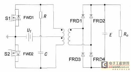
With the increase in the variety of modern electrical equipment for vehicles and the rise in power levels, there is a growing demand for different types of power supplies, including AC and DC sources. The power system needs to...
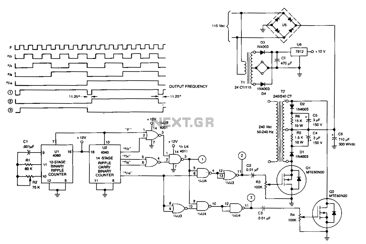
U1 is a 4060 12-stage binary ripple counter that operates as a free-running oscillator, with its frequency of oscillation calculated as 1/2.2 CIR2. The output from U1 is fed into U2, a 14-stage binary ripple counter that generates square-wave...
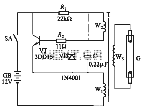
A self-excited transistor inverter circuit is designed for improved performance and features a relatively simple schematic. It is suitable for driving fluorescent lamps with a power rating between 8 to 40 watts. This inverter can operate stably even when...
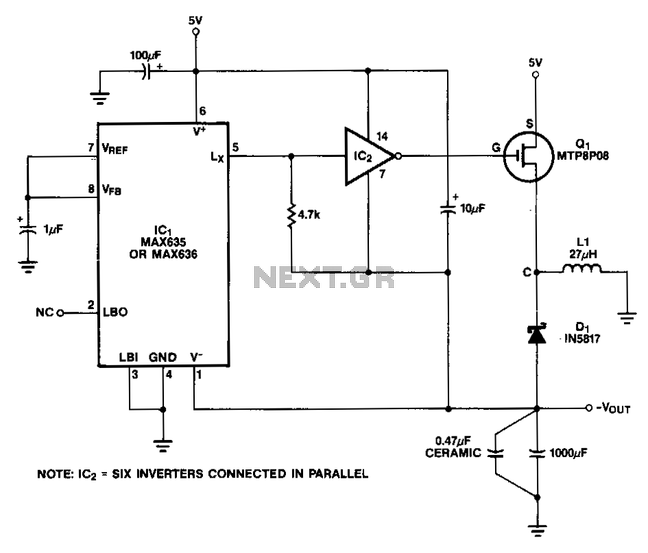
In this circuit, a CMOS inverter, such as the CD4069, is utilized to convert the open-drain Lx output into a signal that is appropriate for driving the gate of an external P-channel MOSFET. The MTP8P03 has a gate threshold...
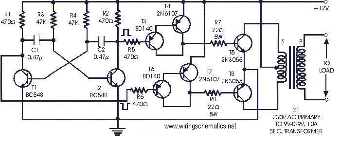
The following circuit is a cost-effective, fully transistorized inverter circuit suitable for driving medium loads in the range of 40 to 60 watts, operating with a 12V, 15 Ah battery or a larger power capacity. Transistors T1 and T2...