
Forward and reverse speed control circuit can be integrated with a brake function

The circuit design in Figure 3173 is integral for applications requiring precise motor control in various operational modes. The inclusion of multiple relays and contactors allows for robust functionality, ensuring that the motor can efficiently switch between mechanical braking, dynamic braking, and reverse operations.
The KI and KI2 overcurrent relays serve a critical safety function, preventing damage to the motor by detecting excessive current conditions that may arise from mechanical jamming or overload situations. The KMi and KM2 contactors facilitate smooth transitions between forward and reverse operations, allowing for flexible motor control in applications such as conveyors or hoists.
Moreover, the KMa and KM4 contactors are essential for engaging the braking systems, with KMa controlling the powered brake and KM4 managing the braking action. The trans pick brake contactor (KMs) is activated during specific conditions to ensure that the motor can quickly halt its operation when necessary.
The time relays (KTi, KT2, KT3) play a pivotal role in timing the actions of the braking and acceleration processes, ensuring that each operation is executed with precision. The dynamic brake relay (KAs) is particularly noteworthy, as it manages the engagement of the dynamic brake contactor (KM3), allowing for controlled energy dissipation during rapid deceleration, which is crucial for maintaining system stability and performance.
Overall, the circuit's design promotes efficient motor control while safeguarding against potential failures, making it suitable for a wide range of industrial applications requiring reliable and responsive motor operations.Figure 3173 is a mechanical braking, dynamic braking, reverse braking function wound rotor induction motor speed can be positive and negative control circuit. Figure, KI, to st all relay (actually overcurrent relay); KI2 overcurrent relay; KMi positive turn contacts; KM2 to reverse contactors; KMa powered brake contactor; KM4 braking contactor; KMs trans pick brake contactor; KM6, KM7 to accelerate contacts; YB brake electromagnet; KAi brake relay; KAz to reverse brake relay; KA3 powered brake relay; KTi, KT2, KT3 the time relay. Wherein the reverse brake relay KA3 is started in reverse braking, the motor slip sa: O when the action, and the turn speed drop close to zero (ie, when s Fl) was released.
Returns must be high coefficient of DC relay. Only action case stall relay KI, in the production of mechanical jamming stall occurs when, due to the rapid emergence of the motor overcurrent. Dynamic brake relay KAs (in essence, a time relay) to control the dynamic brake contactor KM3 action into a step motor control energy consumption rubidium move.
Related Circuits
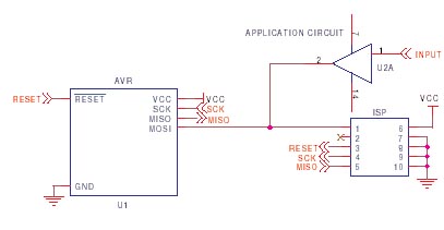
It is crucial to design the PCB layout correctly to enable seamless In-System Programming (ISP) of AVR microcontrollers. This guide addresses common issues encountered and provides typical AVR ISP circuit schematics. It focuses on Serial Programming, known as ISP,...

This circuit functions as a high-quality power supply with a continuously variable stabilized output that can be adjusted to any value between 0 and 30 VDC. It includes an electronic output current limiter that effectively regulates the output current...
This simple FM radio receiver circuit utilizes the TDA7000 integrated circuit (IC), which incorporates nearly all the necessary functions to construct an FM receiver, requiring only a few external capacitors and a tuning circuit. The design employs a straightforward...
The following circuit illustrates a Bass-Treble Tone Control Circuit electronic diagram based on the LM1035N integrated circuit (IC). Features include a 0.3 Vrms input level, 80 dB signal noise ratio, 75 dB volume control, ±15 dB typical tone control,...

These circuits are commonly utilized in robotics to enable DC motors to operate in both forward and reverse directions, as well as to provide an electric brake (short circuit condition). H-bridges can be found as integrated circuits or can...
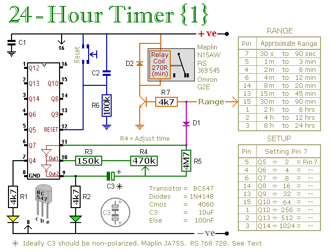
A pair of multi-range timers that provide timing periods extending up to 24 hours and beyond. Both timers are fundamentally identical, with the primary distinction being their relay behavior upon the completion of the timing cycle. Version 1 activates...