
dc VOLTMETER

The described circuit is a versatile voltmeter capable of measuring a wide range of voltage levels, from low millivolt inputs to high voltage levels up to 100 volts. The core of the circuit is an inverting amplifier configuration, which is known for its ability to produce an output voltage that is inversely proportional to the input voltage, scaled by a defined gain factor.
In this design, the gain of the amplifier is adjustable, with a maximum gain of -30 for the 10-mV full-scale range, allowing for precise measurements of very low voltage signals. Conversely, for the 100-V full-scale range, the gain is significantly reduced to -0.003, which enables the circuit to handle high voltage inputs without saturating the output.
Protection against overvoltage conditions is provided by diodes D1 and D2, which are strategically placed in the circuit to clamp excessive input voltages, thus safeguarding the amplifier from damage. These diodes are rated to handle input voltages up to 500V when the circuit is set to the 10-mV range, making the circuit robust against accidental overvoltage situations.
It is important to note that if continuous operation under high overvoltage conditions is anticipated, the power rating of the variable resistor RV should be carefully evaluated and adjusted accordingly. This ensures that the resistor can handle the heat generated during operation without compromising the integrity of the circuit.
Overall, this wide-range voltmeter circuit is designed for flexibility and safety, making it suitable for various applications that require accurate voltage measurement across a broad spectrum of input levels. Proper implementation of this circuit can lead to reliable performance in both laboratory and field environments.A wide-range voltmeter circuit. This inverting amplifier has a gain varying from -30 for the 10-mV full-scale range to -0. 003 for the 100-V full-scale range. Diodes D1 and D2 provide com-plete amplifier protection for input overvoltages as high as 500V on the 10-mV range, but if over-voltages of this magnitude are expected under continuous operati on, the power rating of RV should be adjusted accordingly 🔗 External reference
Related Circuits
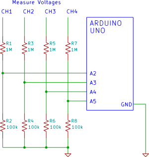
A four-channel voltmeter that displays voltage readings in a software application running on a computer. An Arduino reads the voltages and sends them to an application written in the Processing language. The described circuit comprises a four-channel voltmeter system that...
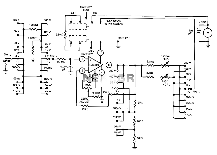
This voltmeter utilizes several beneficial characteristics of the CA3160 BiMOS operational amplifier. It offers voltage measurement capabilities ranging from 10 mV to 300 V. The circuit is powered by a single 8.4-V mercury battery and, at zero input, consumes...
Building a serial voltage meter to measure from 0 to 5 volts DC is straightforward. Utilizing MeLabs PicBasic and Microsoft Visual Basic Version 5 Pro is essential, as the MSComm control required for communication is not available in the Visual...
Diode detectors are good at changing AC into DC, even at high frequencies. The main problem with diode detectors have inherent nonlinearities, particularly for small signals. To minimize the effects of the nonlinearities, a preamplifier boosts the amplitude of...
The circuit was designed to create a high-impedance voltmeter capable of measuring Direct Current (DC) voltages across various types of circuits. The high-impedance voltmeter circuit typically employs operational amplifiers (op-amps) configured in a non-inverting arrangement to ensure minimal loading on...
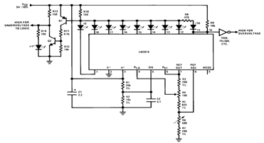
By utilizing several resistors, LEDs, and the LM3914 bar/dot display driver IC, it is possible to create a straightforward 5V voltmeter monitor circuit. This circuit offers TTL-compatible undervoltage and overvoltage warning signals. A complete circuit schematic is available below. The...