
Serial Voltmeter using the PIC16C71
To construct a serial voltage meter, the following components and steps are necessary:
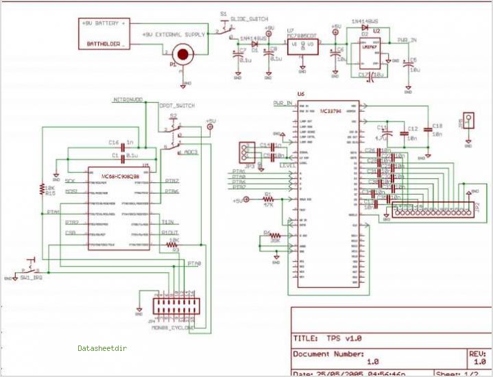
1. **Microcontroller Selection**: The PIC16C71 is selected for its integrated A/D converter, which allows for direct measurement of analog voltage levels. This microcontroller can effectively convert the input voltage into a digital signal that can be transmitted serially to a PC.
2. **Analog Input Configuration**: The microcontroller’s pins 17, 18, 1, and 2 will be configured as analog inputs (AIN0 to AIN3). These pins will receive the voltage signals that need to be measured. Proper configuration in the firmware is essential to ensure accurate readings from the A/D converter.
3. **Programming Environment**: MeLabs PicBasic will be used to write the firmware for the PIC16C71. This programming environment is user-friendly and allows for straightforward manipulation of the microcontroller's features, including the A/D converter.
4. **Serial Communication Setup**: Microsoft Visual Basic Version 5 Pro is required to develop the PC interface. The MSComm control in Visual Basic is crucial for establishing serial communication between the microcontroller and the PC. This control allows for the transmission of the measured voltage values from the microcontroller to the PC for display and analysis.
5. **Power Supply Requirements**: Ensure that the microcontroller is powered adequately, typically with a regulated supply of 5 volts. The voltage meter should also include filtering capacitors to stabilize the power supply and reduce noise in the measurements.
6. **Circuit Design**: The schematic will include the PIC16C71 connected to the analog inputs, with resistors as necessary for voltage division if higher voltages are to be measured. Additionally, a serial connection (RS-232 or USB) will be established to connect the microcontroller to the PC.
7. **Calibration**: After assembling the circuit, calibration is necessary to ensure that the voltage readings are accurate. This may involve comparing the measured values against a known standard and adjusting the software accordingly.
By following these steps and utilizing the specified components, a functional serial voltage meter capable of measuring DC voltages from 0 to 5 volts can be successfully built. The integration of hardware and software components will facilitate real-time data monitoring and analysis, making this project an excellent introduction to microcontroller applications in electronics.Building a serial voltage meter to measure from 0 to 5 volts DC is actually pretty easy. Using MeLabs PicBasic, and Microsoft`s Visual Basic Version 5 Pro. You need Visual Basic Pro version because you will have to use Basic`s MSComm control. This control is not available in the Visual Basic 5 Learning Edition. The PIC16C71 simplifies the task even more by having a built in A/D converter. Pins 17, 18, 1, 2 are the analog inputs AIN0, AIN1, AIN2, AIN3 respectively. Disclaimer All files are found using legitimate search engine techniques. This site does not and will not condone hacking into sites to create the links it list. We will and do assume that all links found on the search engines we use are obtained in a legal manner and the webmasters are aware of the links listed on the search engines. If you find a URL that belongs to you, and you did not realize that it was "open to the public", please use the report button to notify the blogmaster of your request to remove it or it will remove within 24 hours.
This is not an invitation for webblog haters to spam with requests to remove content they feel that is objectionable and or unacceptable. Proof of URL ownership is required. NOTICE: This Blog Has Already Been Reviewed And Accepted By Blogger. com 🔗 External reference
Related Circuits

The term VCXO refers to a Voltage Controlled Crystal Oscillator. The frequency of this oscillator can be fine-tuned by varying the control voltage. VCXO clock generators are utilized in a range of applications, including digital telecommunications. VCXO circuits are essential...

This design circuit is for audio graphic equalizers, which are commonly found in commercial products, yet circuits for them are rarely published. The circuit features a simple design that requires an operational amplifier (op-amp) to amplify the input signal....

Phase Lock Loop (PLL) FM Detector with 565 PLL IC. The circuit diagram and internal structure of the PLL IC 565 are shown in the given figures. The Phase Lock Loop (PLL) FM Detector utilizing the 565 PLL IC is...
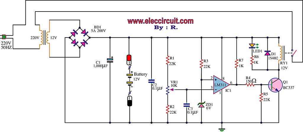
The best 12 Volt battery charger circuit is an automatic system that activates when the battery voltage falls below a specified threshold. This 12 Volt battery charger circuit is designed to efficiently charge lead-acid batteries while ensuring safety and longevity....
This circuit can be used for detecting infrared light; for example, it is utilized for detecting infrared band light signals in a spectrophotometer. The amplifier output voltage Vo is given by the formula Vo = Is·Rd·Rf/Ri, where Is is...
The TPA2011D1 is a 3.2-W high-efficiency, filter-free Class-D audio power amplifier housed in a 1.21 mm x 1.16 mm wafer chip scale package (WCSP) that requires only three external components. This amplifier features 95% efficiency, an 86-dB power supply...