
decibel meter

The described circuit operates within a specific sound pressure level range, utilizing an 8-ohm speaker as a transducer to detect sound waves. When sound waves hit the speaker, it converts acoustic energy into electrical signals. These signals are then amplified by a transistor stage, which enhances the signal strength before it is fed into one section of the LM324 quad op-amp. The LM324 is a versatile operational amplifier that can amplify, filter, and perform various signal processing tasks.
In this application, the LM324 is configured to perform as a voltage comparator. The output of the op-amp is compared against predetermined voltage thresholds that correspond to the sound pressure levels of interest. The three remaining sections of the LM324 are set up to trigger different output states based on the input signal level, effectively creating a multi-level sound level indicator. Each comparator output activates an indicator LED or incandescent lamp when the input sound level exceeds the defined thresholds, spaced approximately 3 dB apart. This provides a visual representation of the sound intensity.
To drive the incandescent lamps, which require more current than the LM324 can provide directly, an additional transistor is included in the design. This transistor acts as a switch, allowing the op-amp output to control a larger current flowing through the lamp, thereby illuminating it when the corresponding sound pressure level is detected. The overall design ensures that the circuit is sensitive and responsive to varying sound levels, making it suitable for applications where sound monitoring is essential.The circuit below responds to sound pressure levels from about 60 to 70 dB. The sound is picked up by an 8 ohm speaker, amplified by a transistor stage and one LM324 op-amp section. You can also use a dynamic microphone but I found the speaker was more sensitive. The remaining 3 sections of the LM324 quad op-amp are used as voltage comparators and drive 3 indicator LEDs or incandescents which are spaced about 3dB apart.
An additional transistor is needed for incandescent lights as shown with the lower lamp.. 🔗 External reference
Related Circuits

A unified thermometric controller that can be programmed with simple scripts, integrating the "classic" thermometer/controller pair. You can build a variety of simple machines with the same hardware and a different script: a charting thermometer, a vending machine that...
When this thermometer is utilized in a room environment, it operates intermittently, maintaining this operational state within the temperature measurement circuit due to the stable internal temperature. The astable multiresonance oscillator is composed of transistors VT1 and VT2, forming...
A circuit of measurement of level based on a typical application of National. The circuit round the IC1 makes input adaptation and amplification with the trimmer TR1 [GAIN]. The circuit round the IC2 makes half-wave rectification of acoustic signal....
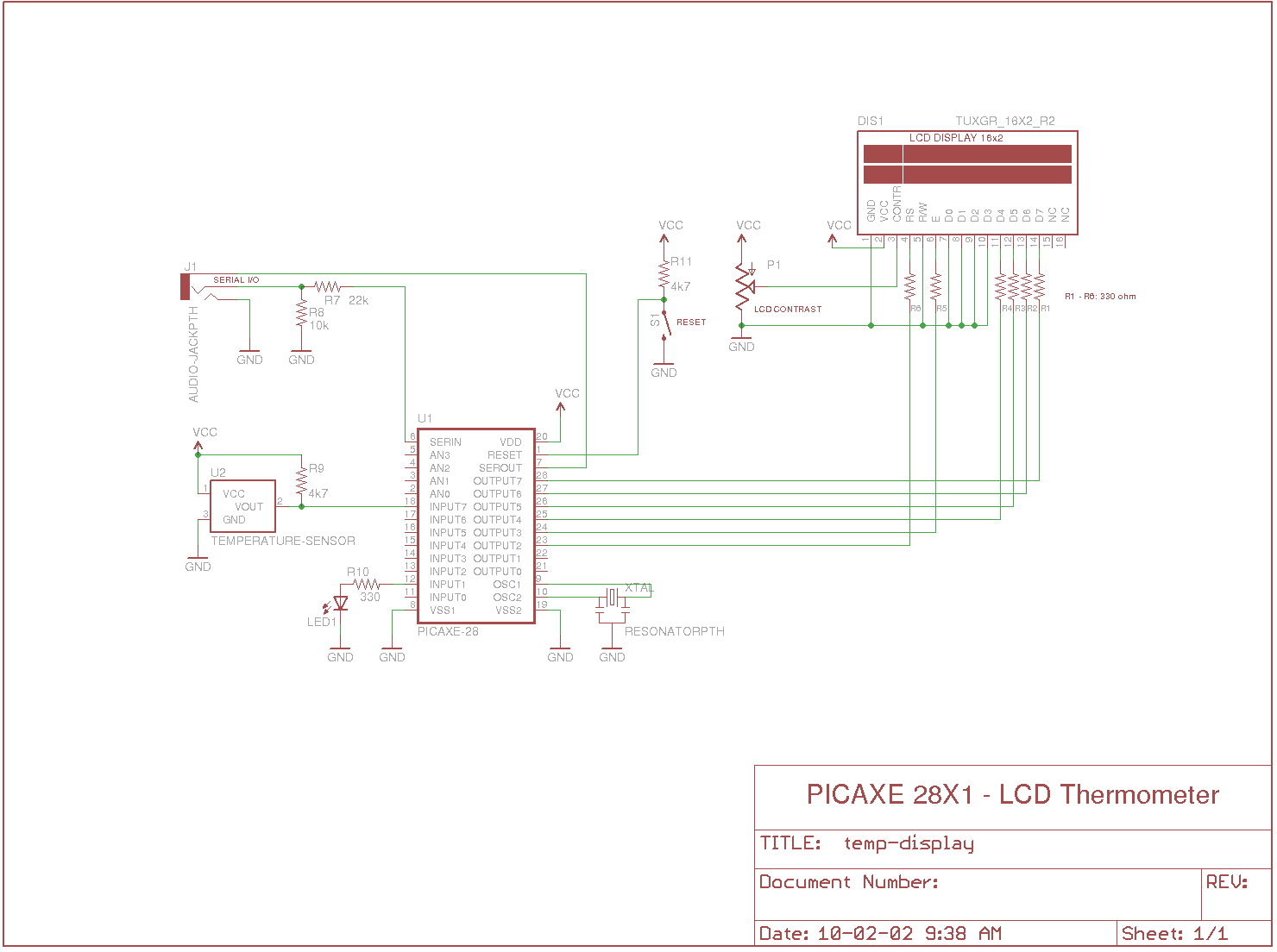
Measures the temperature using the DS18B20 temperature sensor, displays the reading on a 2x16 character LCD, sends the data to a serial terminal, and checks the temperature against predefined limits. The output is set high if the temperature is...
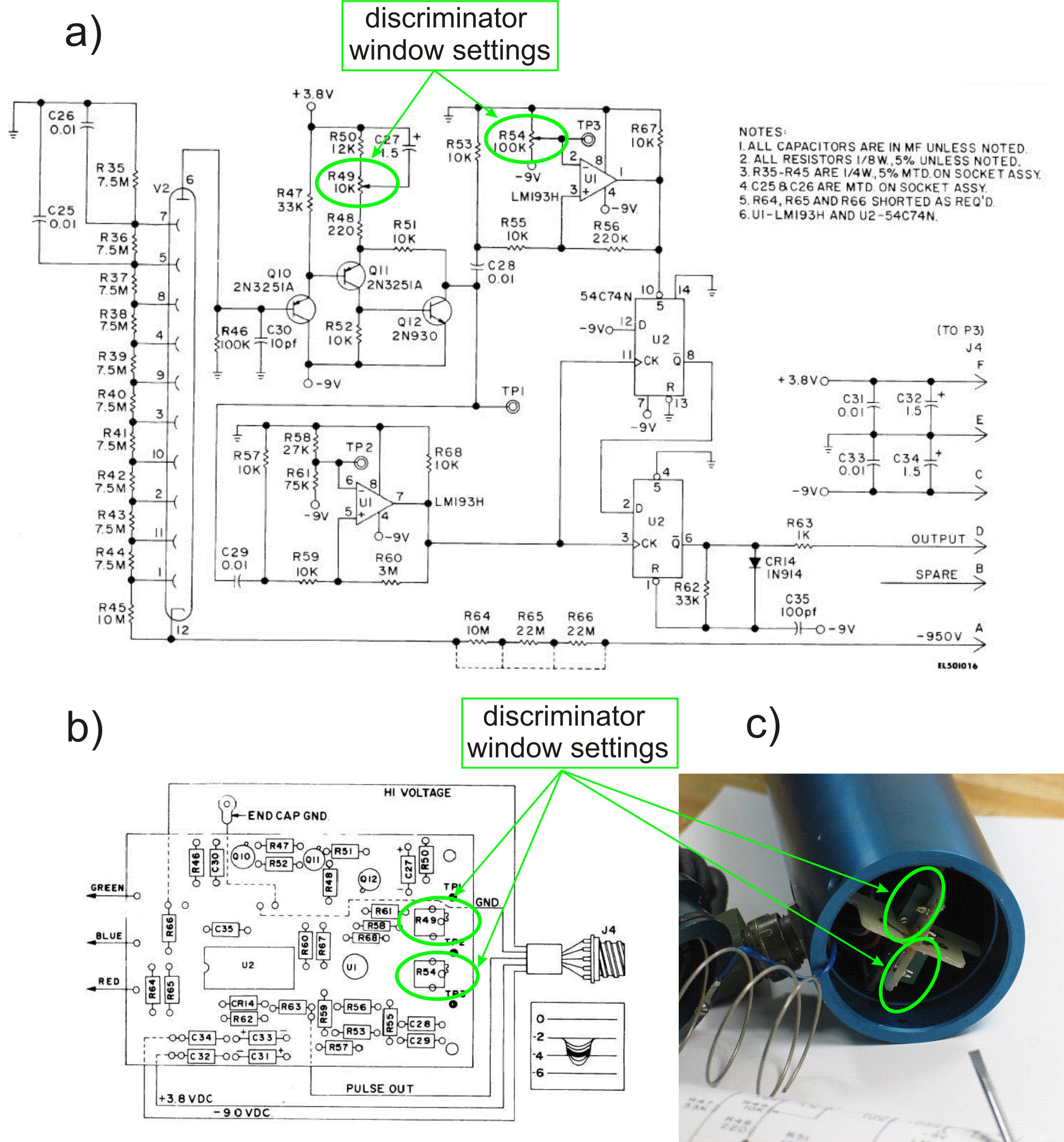
This PDF file presents the schematic diagram of a custom-built circuit designed to drive the PDR-56 probe. A JKL BXA-12579 inverter, typically used for powering cold-cathode fluorescent lamps, serves as the high-voltage power supply. The BXA-12579 generates 1,500 VAC...
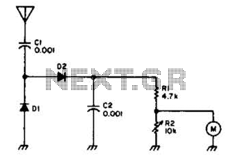
Useful for checking transmitters and antennas, this circuit utilizes a voltage-doubling detector consisting of diodes D1 and D2, which can be HP 5082-2800 hot carrier types or alternatives such as 1N34 or IN82. The circuit incorporates a 100-mA meter...