
20 LED VU meter

Part List
R1-2=10Kohm C1=100uF 25V D1-19=LED 3 or 5mm any colour.
R3-4=10Kohm C2-5=10uF 25V D20-21=1N4148
R5-8-9=1Kohm C3-4=100nF 100V
R6=330Kohm C6=1uF 25V IC1=TL 072
R7=62Kohm IC2=LM3915
TR1=47Kohm Trimmer S1=mini Switch IC3=LM3916
The described circuit is a level measurement system designed for acoustic signals, utilizing integrated circuits (ICs) from National Semiconductor. The circuit is structured around two main operational amplifiers, IC1 and IC2, where IC1 serves as an input stage for adaptation and amplification of the incoming signal. A trimmer potentiometer, TR1, is employed to adjust the gain of this first stage, allowing for fine-tuning of the input signal level to optimize performance.
The output from IC1 is fed into IC2, which performs half-wave rectification of the amplified acoustic signal. This rectification is crucial for converting the AC signal into a usable DC level that can be processed or displayed. The circuit includes a switch, S1, which allows the user to select the type of visual indication from the LED array, providing flexibility in output display options.
Resistors R6 and R7 play a significant role in setting the input signal level, which is specified to be 7.8V with a unity gain from the first stage (IC1). The design anticipates a 3 dB difference in signal levels between the LEDs D10 and D11, which indicates the dynamic range of the measurement system.
Power supply considerations are important in this design, particularly regarding the positive supply rail, which must be capable of providing sufficient current to prevent overload conditions, especially when driving the LED indicators. The inclusion of various capacitors (C1, C2, C3, C4, C5, and C6) serves to stabilize the circuit and filter any noise, ensuring accurate measurement and indication of the acoustic signal levels.
The component list specifies various resistors, capacitors, diodes, and ICs, including the TL072 for the operational amplifier and the LM3915 and LM3916 for LED bar graph and dot display drivers, respectively. This comprehensive design provides a robust solution for measuring and visually indicating acoustic signal levels in a variety of applications. A circuit of measurement of level based on a typical application of National. The circuit round the IC1 makes input adaptation and amplification with the trimmer TR1 [GAIN]. The circuit round the IC2 makes half-wave rectification of acoustic signal. With switch S1, we select the type of indication, that we will have from the LED. With the prices in resistances R6 and R7 that exists in the circuit, the level of signal, in the entry is 7.8V (gain of first stage IC1, is one), and the difference of level between the LED D10-11, should are 3 db. The positive department of supply, should have the possibility of giving more current, one and it is overloaded with the current of LED..
Part List R1-2=10Kohm C1=100uF 25V D1-19=LED 3 or 5mm any colour. R3-4=10Kohm C2-5=10uF 25V D20-21=1N4148 R5-8-9=1Kohm C3-4=100nF 100V R6=330Kohm C6=1uF 25V IC1=TL 072 R7=62Kohm IC2=LM3915 TR1=47Kohm Trimmer S1=mini Switch IC3=LM3916 🔗 External reference
Related Circuits
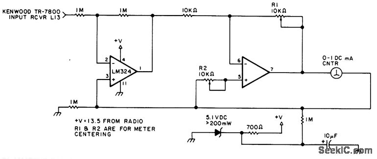
This circuit can be utilized in most FM VHF receivers, with the connection made from the FM discriminator. Each transmitted signal has a unique deviation signature, which can assist in identifying jammers. The described circuit is designed for integration into...
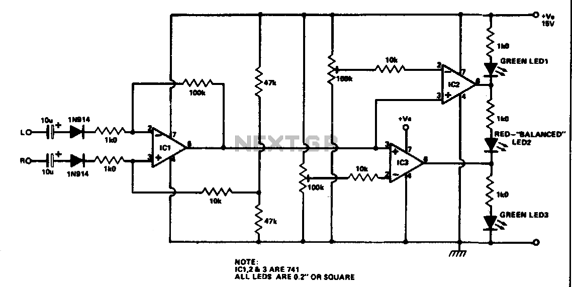
Outputs from each channel are fed to the two inputs of IC1 connected as a differential amplifier. IC2 and IC3 are driven by the output of IC1. The output of IC1 is connected to the non-inverting inputs of IC2...
This circuit is designed to provide an inexpensive way to create a High Impedance Voltmeter while making use of an inexpensive analog or digital multimeter. When measuring voltages in high resistance circuits, the resistance of the voltmeter itself has...
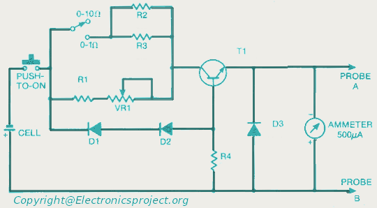
This document provides a circuit diagram for an ohmmeter designed for low resistor measurements. Additional resources, including over 300 electronic circuits, are available on this site. The ohmmeter circuit is primarily used to measure the resistance of low-value resistors, typically...
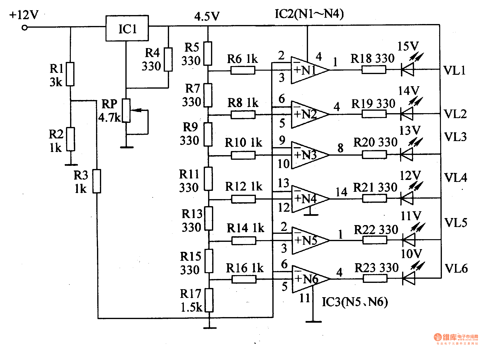
This document introduces an LED car voltmeter constructed using the op-amp LM312 and LED components. It is designed to display six voltage levels ranging from 10V to 15V, with each level representing a 1V increment. The working principle of...
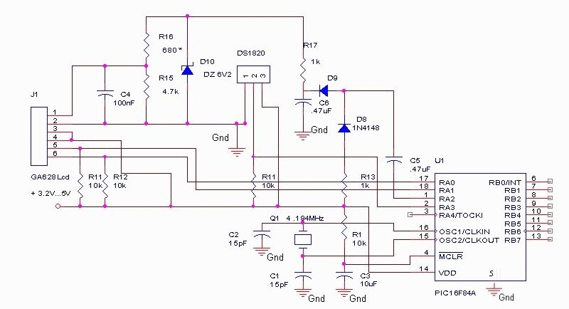
The DS18S20 digital thermometer offers a precision of 0.5 °C, with the SCRATCHPAD being read every 800 ms. Capacitors C5 and C6, along with diodes D8 and D9, form a voltage doubler to power the LCD panel. The DS18S20...