
Decimal to BCD Convertor Keypad

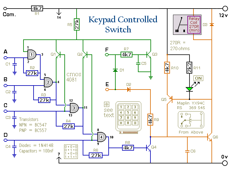
The described circuit functions as a binary-coded decimal (BCD) converter, which translates the pressed key value into a BCD output format. The outputs A, B, C, and D represent the four bits of the BCD code, allowing for the representation of decimal digits 0 through 9. When one of the 12 keys is pressed, the corresponding BCD value is generated and held at the outputs until a different key is pressed, which then updates the displayed value.
For applications requiring an extended range, the circuit can accommodate up to 16 keys, yielding a full hexadecimal to BCD conversion. This enhancement enables the representation of values from 0 to 15 in hexadecimal format, which corresponds to 0000 to 1111 in binary.
The initial design outputs a signal only while the key is actively pressed, which may not be suitable for all applications. To create a latching output that maintains the last pressed key's value even after the key is released, modifications are necessary. Each CMOS AND gate in the circuit is configured with its free input connected to the positive supply voltage (Vcc). This configuration allows the circuit to maintain the last output state by leveraging the characteristics of the CMOS technology, which consumes minimal power and provides high noise immunity.
Additionally, a resistor (R1) is introduced in the circuit to help manage the timing and stability of the latching mechanism. This resistor can influence the charging and discharging rates of any capacitive elements present in the circuit, thereby affecting the response time and the overall performance of the latch. The precise values of R1 and any other components will depend on the specific requirements of the application, such as the desired response time and the load characteristics of the output.
Overall, this circuit design provides a robust solution for converting key presses into a stable BCD output, with the flexibility to extend its functionality through the incorporation of additional keys and latching mechanisms.When any particular key is pressed, its value will appear in BCD form at the outputs (A, B, C & D). It will remain there until another key is pressed. The 12 keys produce outputs up to "1011". Extended to 16 keys, the circuit will give the full HEX to BCD conversion. The above circuit produces an output ONLY while the input switch is depressed. To make a convertor with a latched output, the following modifications are made. Each CMOS `AND` gate has its free input tied to Vcc, and by the action of R1 through 🔗 External reference
Related Circuits
This tutorial explains how to read the content of a microcontroller's flash memory. The source microcontroller reads the memory content and displays it on the LEDs. The content consists of the program stored in the microcontroller's memory. This step...
The integrated circuit (IC) is a quad 2-input "AND" gate, specifically a CMOS 4081. These gates output a HIGH signal only when both inputs are HIGH. When the key connected to pin E is pressed, current flows through resistor...
Speaker relay delay controlling circuit for audio amplifier The speaker relay delay controlling circuit is designed to manage the connection between an audio amplifier and loudspeakers, ensuring that the speakers are only activated after a predetermined delay. This delay is...
The differential outputs are balanced and designed to drive long lengths of coaxial cable, stripline, or twisted pair transmission lines with characteristic impedances ranging from 50 ohms to 500 ohms. Differential transmission is superior to single-wire transmission as it...
This circuit will generate a smaller DC output voltage from a larger DC input voltage. It is quick and simple to make and by changing the value of the zener diode, the circuit can be universally adapted to provide...
The alarm will switch off when the 4 keys connected to "A,B,C,D" are pushed in the right order. The circuit works because each gate stands upon its predecessor. If any key other than the correct key is pushed, then...