
Electronic Keypad

The circuit described operates as a sequential key code entry system, utilizing a series of logic gates to validate the input sequence. The primary component is the CMOS 4081 integrated circuit, which contains four dual-input AND gates. Each gate serves as a stage in the sequence, where the output of one gate is connected to the input of the next, thus creating a chain of dependencies.
The process begins with four keys designated as A, B, C, and D. Each key must be pressed in the correct order for the alarm to deactivate. When a key is pressed, it provides a HIGH signal to the corresponding input of the first AND gate. The output of this gate will only be HIGH if both of its inputs are HIGH, which means that the previous key in the sequence must have been pressed correctly.
If an incorrect key is pressed, the first gate's output will drop to LOW, effectively disabling the entire sequence. This design relies on the principle of cascading logic gates, where each gate must be satisfied for the subsequent gate to function correctly.
Pin 1 of the first gate is held HIGH by a resistor R4, ensuring that the sequence can begin. Resistor R1 and diode D1 are used in conjunction with the key connected to input E. When this key is pressed, it allows current to flow through R1, turning on transistor Q5. This transistor acts as a switch that energizes a relay, which can be used to control the alarm system.
The relay's activation signifies that the correct sequence of keys has been entered, allowing the alarm to switch off. The design emphasizes the importance of correct timing and order in the key presses, making it a secure method for deactivating the alarm while preventing unauthorized access through incorrect entries.The alarm will switch off when the 4 keys connected to "A,B,C,D" are pushed in the right order.The circuit works because each gate `Stands` upon its predecessor.If any key other than the correct key is pushed, then gate 1 is knocked out of the stack, and the code entry fails. Pin 1 is held high by R4. The IC is a quad 2 input "AND" gate, a CMOS 4081. These gates only produce a HIGH output, when BOTH the inputs are HIGH. When the key wired to `E` is pressed, current through R1 and D1 switchs Q5 on.The relay energises; and Q5 is ' 🔗 External reference
Related Circuits
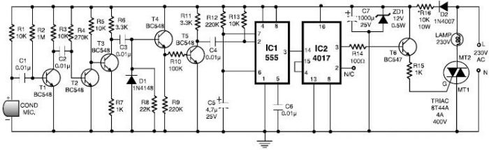
This 555 timer clap switch circuit electronic project is designed using common electronic components. The circuit operates from a distance of up to 10 meters from the microphone. The signal from the microphone is amplified by transistors T1, T2,...
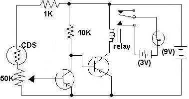
This circuit was submitted by Adam from Canada who is still at school. I have provided the text. The two transistors are used as a direct coupled switch, Adam used 2SC711 but any general purpose transistor will do e.g....
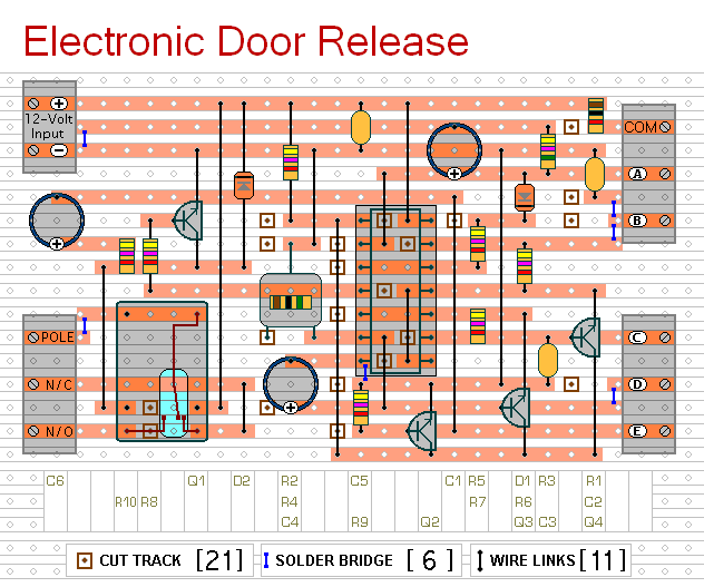
This circuit is designed to operate an electrical door-release mechanism, but it can be adapted for other applications. Upon entering a four-digit code of the user's choice, the relay will energize for a preset duration. The relay contacts can...
Most of the source code for this project is based on the Telecard reader project from my website. The components are few and ordinary, which means they are low-cost and easy to find. The "keys" are empty or non-telecards...
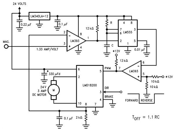
The LMD18200 3A H-Bridge, designed by National Semiconductors, can be used to create a simple motor controller electronic project suitable for motion control applications. This component is ideal for driving both DC and stepper motors, accommodating peak output currents...
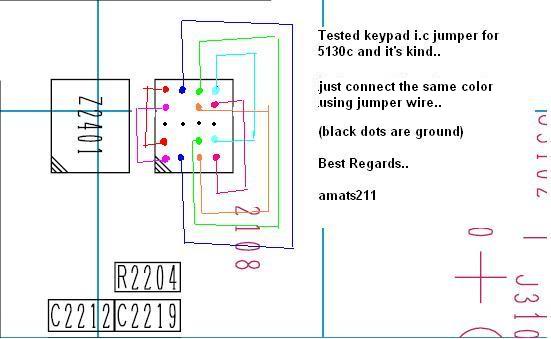
The Nokia 5130 keypad jumper requires following a specific diagram. It has been tested recently, and after implementing the jumper, all keypads are functioning correctly. The Nokia 5130 mobile phone features a keypad that can occasionally experience issues due to...