
Delay electronic doorbell circuit - touch doorbell amplifier circuit

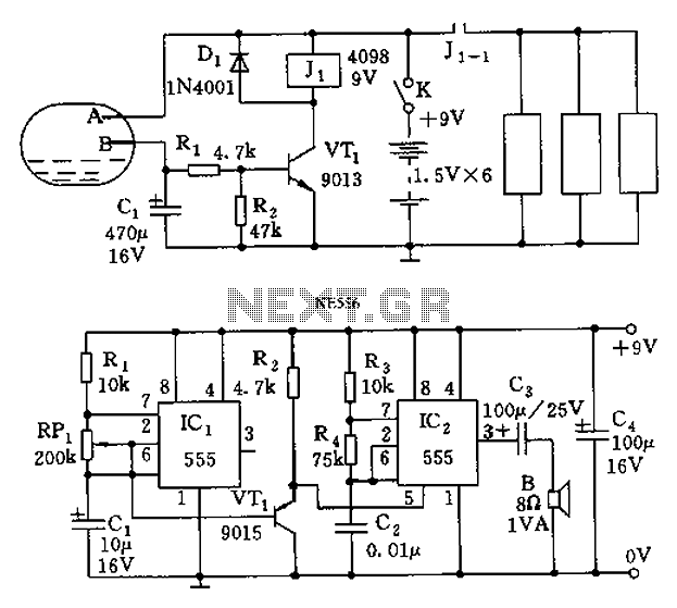
The delay electronic doorbell circuit is designed to provide a user-friendly interface for doorbell activation, utilizing a touch-sensitive amplifier circuit. This circuit typically incorporates a touch sensor that detects user interaction, triggering the doorbell chime after a predetermined delay. The delay feature allows the user to ensure that the circuit does not activate immediately upon touch, providing a buffer period that can help prevent accidental triggering.
The circuit generally consists of several key components: a touch sensor, a microcontroller or timer IC to manage the delay, a power supply, and an output driver connected to the doorbell chime. The touch sensor can be a capacitive or resistive type, which detects changes in capacitance or resistance when a user touches the designated area. The microcontroller or timer IC is programmed to initiate a delay sequence upon receiving a signal from the touch sensor.
Upon activation, the microcontroller starts a timer that counts down the specified delay time. Once the delay period elapses, the microcontroller sends a signal to the output driver, which energizes the doorbell chime. The output driver may consist of a relay or a transistor, depending on the power requirements of the chime. The power supply must provide adequate voltage and current for all components, ensuring reliable operation.
In summary, the delay electronic doorbell circuit with a touch doorbell amplifier enhances user experience by integrating touch sensitivity and delay functionality, making it a practical solution for modern doorbell applications.Delay electronic doorbell circuit - touch doorbell amplifier circuit
Related Circuits
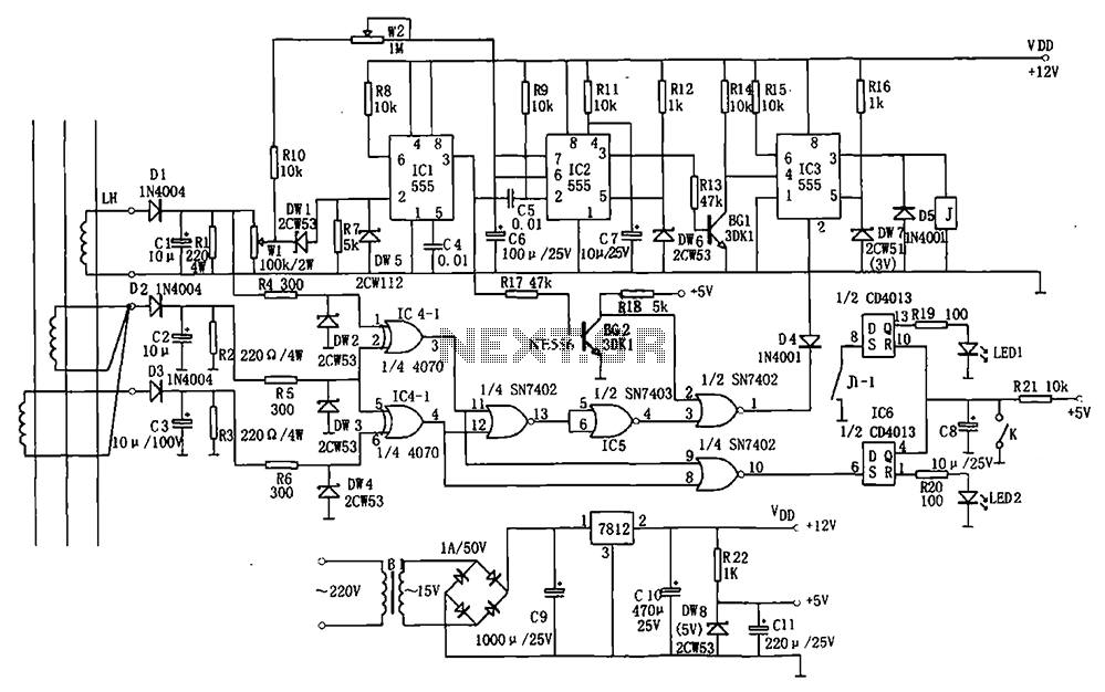
The electrical equipment overload and phase failure protection circuitry includes a +12V and +5V DC power supply, an AC transformer, voltage comparators, timers for blockade, a relay control circuit, and a phase loss protection circuit. The DC power supply...
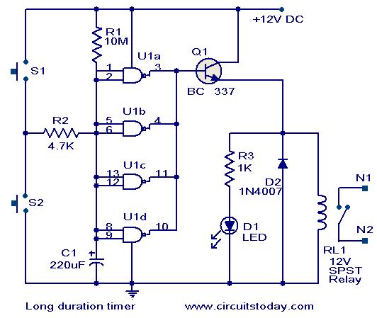
This timer circuit is designed to turn off a specific device after approximately 35 minutes. It can be utilized to switch off appliances such as radios, TVs, fans, and pumps after a predetermined duration of 35 minutes, contributing to...
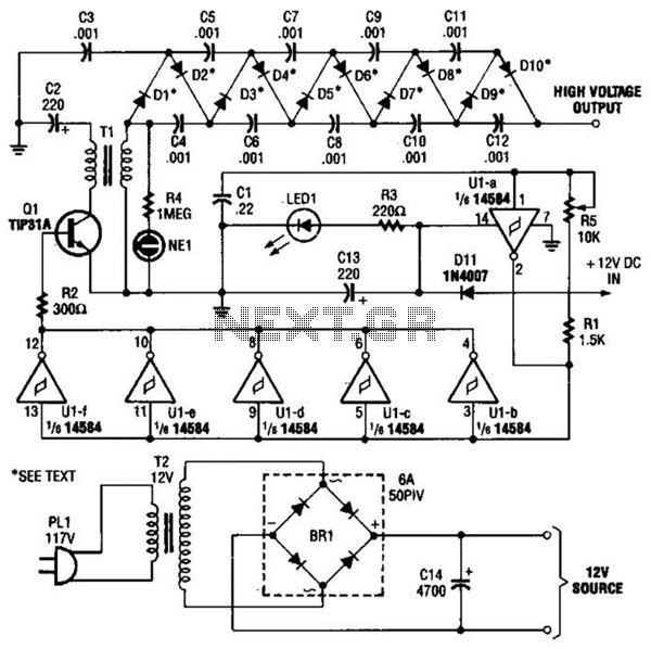
In the miniature high-voltage DC generator, the circuit receives input from a 12 V DC power supply, which is amplified to produce a 10,000 V DC output. This process induces a pulsating signal of opposite polarity in the secondary...
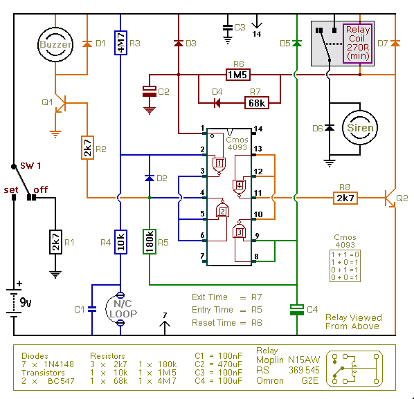
This is an improved version of the basic Garage/Shed Alarm. The Entry and Exit delays have been extended to approximately 30 seconds, and a timed Siren cut-off along with an automatic reset feature has been added. Additionally, the LED...
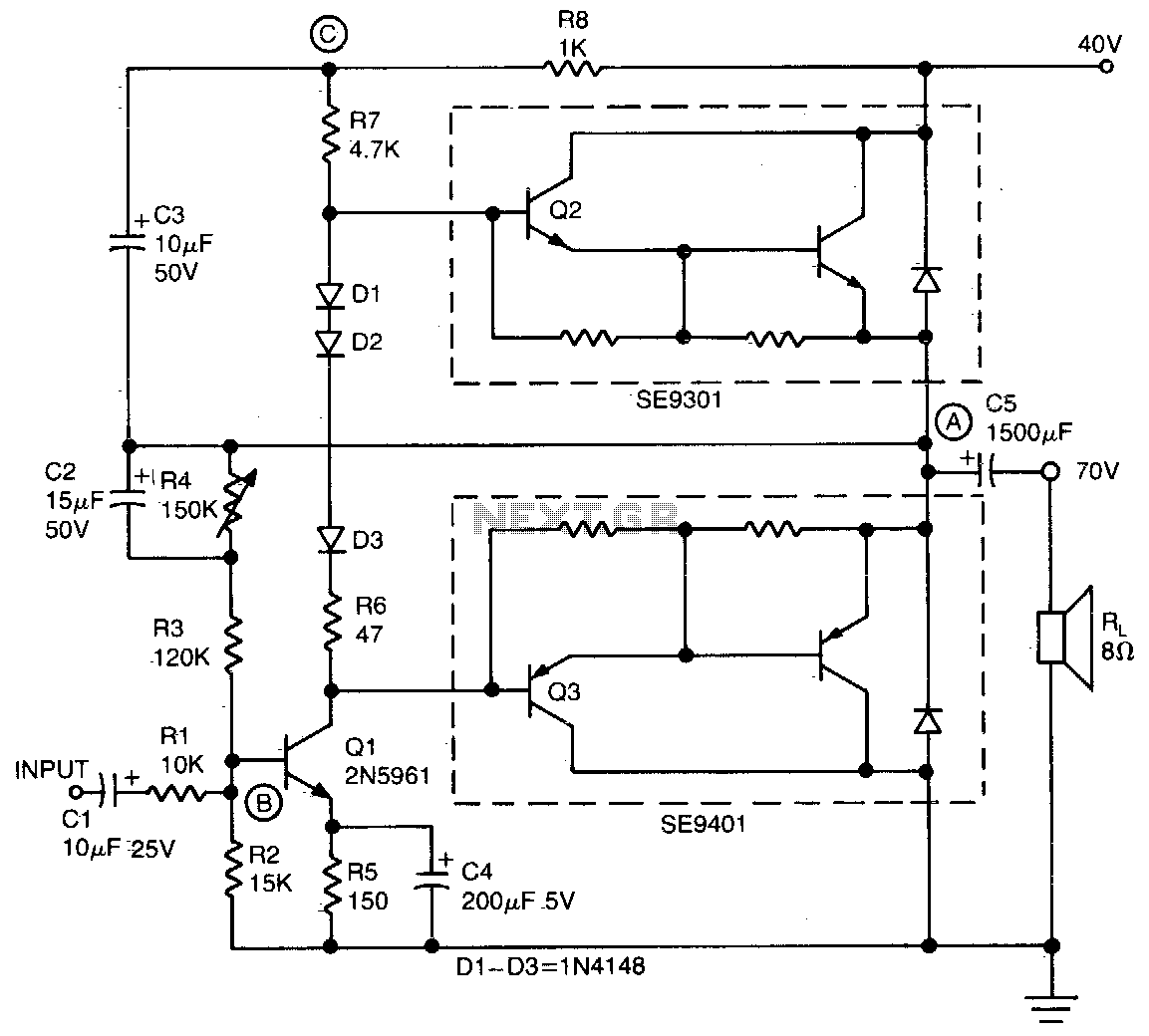
This simple and inexpensive audio amplifier can be constructed using a couple of TO-220 monolithic Darlington transistors for the push-pull output stage. The frequency response is flat within 1 dB from 30 Hz to 200 kHz, with typical harmonic...
The call is triggered by the position sensing circuit, which activates the control circuit and SOS alarm circuit. This system is designed for critically ill patients or to assist disabled individuals in the event of a fall. A position...