
Delay On Circuit

This delay-on circuit is designed to enhance the protection of LCD and Plasma TVs by mitigating the risk posed by voltage spikes that can occur in SMPS (Switched-Mode Power Supply) systems. The circuit typically employs a relay or a solid-state switch that engages the power supply to the TV after a predetermined delay, allowing transient voltage conditions to stabilize before the TV is powered on.
The circuit can be implemented using a simple timer IC, such as the 555 timer, configured in monostable mode. When the power is applied, the timer begins its timing cycle, which can be adjusted using an external resistor and capacitor. Once the timing period elapses, the output of the timer activates the relay or switch, connecting the power supply to the TV.
To ensure reliability, the circuit should include protection components such as a flyback diode across the relay coil to prevent back EMF from damaging the timer IC. Additionally, a fuse or circuit breaker can be integrated to protect against overcurrent situations.
The delay-on feature not only safeguards the TV against potential damage but also contributes to the longevity of the device by reducing wear on the power supply components. This circuit is an effective solution for users looking to enhance the resilience of their electronic devices against power fluctuations.Protect your LCD or Plasma TV with this tiny delay on circuit. The SMPS based power supply of these modern electronic devices is vulnerable to spikes in t. 🔗 External reference
Related Circuits
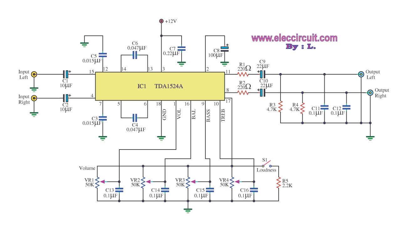
The stereo tone control circuit utilizes the integrated circuit TDA1524A. This IC serves as the central component in the design. The TDA1524A is a versatile integrated circuit designed for audio applications, particularly in tone control systems. It features a dual-channel...
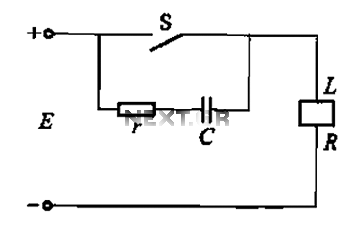
A resistor-capacitor circuit designed to prevent spark blowout. The coil's magnetic energy is converted into electrical energy stored in the capacitance C, effectively suppressing sparks and enhancing safety. The circuit is capable of functioning normally even with reverse polarity....
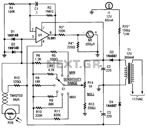
The Meter Ml is a +/-50-uA zero-center D'Arsonval meter movement driven by Ul, a TL081 FET op amp, through R3. The gain of Ul is set to 11 using resistors R1 and R2, while capacitor C1 restricts the bandwidth...
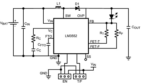
For this LED driver electronic project, a DC power supply circuit is required to provide an output voltage between 2.7V and 5.5V. The supply voltage must be applied between Vin and GND. The T/F jumper connects the T post...
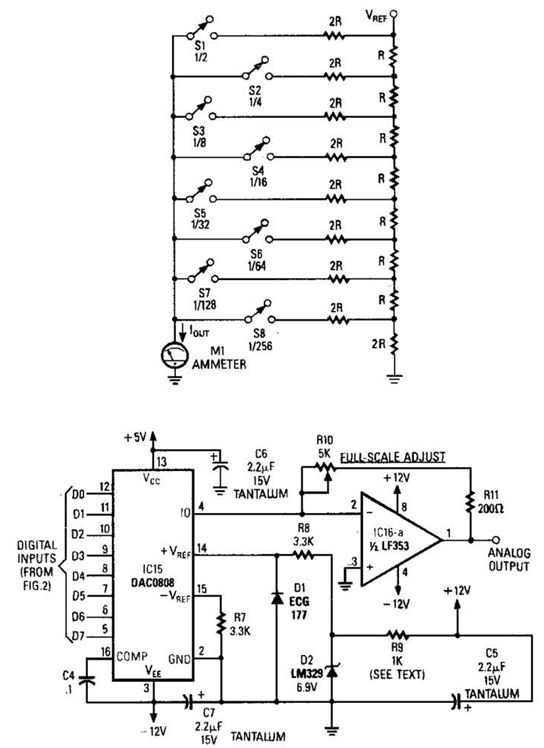
Figure A illustrates an R/2R resistor ladder. Each closed switch increases the current output. A basic channel A/D converter is depicted in Figure B. The voltage reference (D2) is shared among all channels, while the value of the dropping...
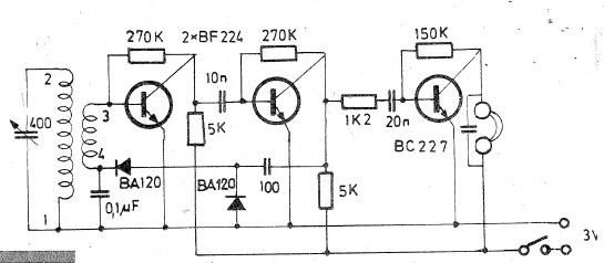
Oscillating circuits (coils) are constructed on a ferrite bar. For long wave reception, winding "1-2" consists of 135 turns, while winding "3-4" has 20 turns. For medium wave reception, winding "1-2" has 75 turns, and winding "3-4" has 7...