
Delayed start for mains equipment

The time selection is done by pressing one of SW3 (90 minutes), SW4 (3 hours), SW5 (6 hours). When pressed, the appropriate input (2 to 4) will go to logic 0. The button SW2 is connected to 1, and is used to manually turn off the relay, canceling the effect of the timer. Another button, SW1, has the opposite effect, and it works by resetting the chip. The Nutchip oscillates at a frequency of 4MHz, determined by 'ceramic resonator OSC1. The CN1 connector is used only for the suid of the chip, and you can omit it if you pre-program the chip to another circuit. We suggest you keep it, not only because it is easier to change the truth table on the fly. Through the interface, since you can "see" the inputs and outputs on your PC using the software Nutchip Commander: a useful tool to understand very thoroughly how to "run" the chip. To turn on an appliance consuming large amounts (more than 2.1 amps, approximately 350 watts) using the power relay (switch) into alternating current. You find them in electrical stores. A power relay does not directly with the pilot is Nutchip, it interposes a rather smaller relay (the relay driver, in our case RE1). To realize this circuit you should prepare a printed circuit board shown in the drawing below. You can use a matrix board (following the grid design, that is the pitch of the holes) only if you are really experts in this technique, because the leaders of the relay are dangerous voltages to 220V. To comply with the insulation, you should absolutely remove contaminated by spacers all piazzoline from the area highlighted in yellow (use a cutter or a Dremel with a round cutter).
Begin to assemble the components lower (resistance), rising gradually to the highest and big. Better to use a socket to IC1. Beware not to reverse the polarity of the LEDs and integrated IC1 and IC2, the transistors, diodes. If in doubt, check the components page for details. It's the pilot relay that turns on the power relay, according to the diagram at right. Ask always your electrician which model is best suited for your application. The circuit draws the voltage stabilized at 5 volts from an external terminal to be connected to the heads of the M1. The diodes D2, D3, D4, and D5 in the classic configuration bridge rectifies the alternating current, which is then leveled by C4. The IC IC2, a 7805, stabilizes the voltage to a fixed 5-volt.
The described circuit functions as a timer-controlled relay system, primarily utilizing the Nutchip microcontroller to manage timing operations and relay actuation. The relay RE1 is pivotal for controlling the power to an appliance, with its configuration allowing for either a normally open (NO) or normally closed (NC) operation based on user requirements. In applications where the appliance should turn on after a specified delay, the NO contact is employed, while the NC contact is used when the intent is to cut power at the end of the timing interval.
The user interface consists of multiple switches (SW1 to SW5) that allow for time selection and manual control. The circuit's design incorporates a straightforward method for time selection, where pressing one of the designated switches sets the corresponding input to a logic low state, enabling the desired timing function. The manual override provided by SW2 allows for immediate relay deactivation, while SW1 serves to reset the entire system, providing flexibility in appliance control.
Power management is addressed through the use of a 7805 voltage regulator, ensuring that the Nutchip and associated components receive a stable 5V supply. The rectification of AC voltage is handled by the bridge rectifier configuration, ensuring that the circuit can operate reliably under varying input conditions. The design emphasizes safety, particularly in handling high voltages associated with the relay contacts, necessitating careful PCB layout and component selection to prevent accidental contact and ensure user safety.
Overall, the schematic presents a robust solution for timed appliance control, leveraging both digital and analog components to create a versatile and user-friendly system.The schematic requires few components, because the timer function has been incorporated by Nutchip. For once, from the start, made up of contacts of the relay RE1 connected to terminal M2. If we turn on an appliance at the end of time, we will use the relay contact is signed (normally open) and the COM contact (common). But if we are interested in off the load at the end of time we will use the pair of contacts COM and NC (normally closed).
The relay RE1 is driven by Nutchip junction 4 of the transistor TR1, and is suitable for connecting devices up to 300-350W of power. For higher powers use a power relay out, as described below. In addition to turning on the relay RE1, the transistor driver DL4 also the LED, which lights up whenever the relay is energized. The other outputs of Nutchip, OUT1 to OUT3 are connected to as many LEDs that indicate the delay time selected.
The time selection is done by pressing one of SW3 (90 minutes), SW4 (3 hours), SW5 (6 hours). When pressed, the appropriate input (2 to 4) will go to logic 0. The button SW2 is connected to 1, and is used to manually turn off the relay, canceling the effect of the timer. Another button, SW1, has the opposite effect, and it works by resetting the chip. The Nutchip oscillates at a frequency of 4MHz, determined by ' ceramic resonator OSC1. The CN1 connector is used only for the suid of the chip, and you can omit it if you pre-program the chip to another circuit.
We suggest you keep it, not only because it is easier to change the truth table on the fly. Through the interface, since you can "see" the inputs and outputs on your PC using the software Nutchip Commander: a useful tool to understand very thoroughly how to "run" the chip. To turn on an appliance consuming large amounts (more than 2.1 amps, approximately 350 watts) using the power relay (switch) into alternating current.
You find them in electrical stores. A power relay does not directly with the pilot is Nutchip, it interposes a rather smaller relay (the relay driver, in our case RE1). To realize this circuit you should prepare a printed circuit board shown in the drawing below. You can use a matrix board (following the grid design, that is the pitch of the holes) only if you are really experts in this technique, because the leaders of the relay are dangerous voltages to 220V.
To comply with the insulation, you should absolutely Remove contaminated by spacers all piazzoline from the area highlighted in yellow (use a cutter or a Dremel with a round cutter). Begin to assemble the components lower (resistance), rising gradually to the highest and big. Better to use a socket to IC1. Beware not to reverse the polarity of the LEDs and integrated IC1 and IC2, the transistors, diodes. If in doubt, check the components page for details. It 's the pilot relay that turns on the power relay, according to the diagram at right. Ask always your electrician which model is best suited for your application. The circuit draws the voltage stabilized at 5 volts from an external terminal to be connected to the heads of the M1.
The diodes D2, D3, D4 and D5 in the classic configuration bridge rectifies the alternating current, which is then leveled by C4. The IC IC2, a 7805, stabilizes the voltage to a fixed 5-volt, 🔗 External reference
Related Circuits
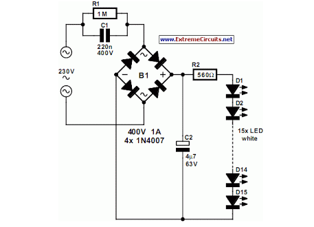
An array of white LEDs can serve as an effective small lamp for the living room. LED lamps are commercially available. LED arrays are increasingly popular for providing ambient lighting in residential spaces. The use of white LEDs in a...

While owning a modern NiCd battery charger is advantageous, there may still be instances where an incompatible battery is encountered, such as one with an unusual voltage requirement or a need for a higher charging current than what a...
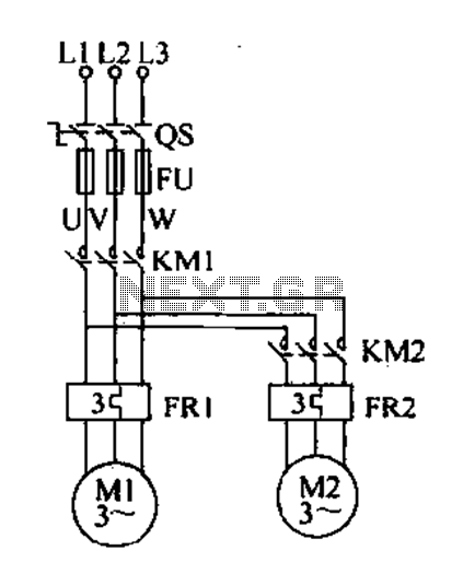
Delay starting a motor control circuit The motor control circuit designed for delayed activation incorporates a timing mechanism that ensures the motor does not start immediately upon receiving power. This is particularly useful in applications where a staggered startup...
A novice in circuit creation is utilizing a 12V battery regulated to 2mA with an LM334Z current regulator. Documentation for the current regulator is available. The LM334Z is a versatile current regulator that can be used in various applications requiring...
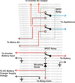
This inquiry has been presented multiple times on this blog regarding the implementation of a changeover selector switch for the automatic toggling of an inverter when AC mains power is available, and vice versa. The system must also enable...
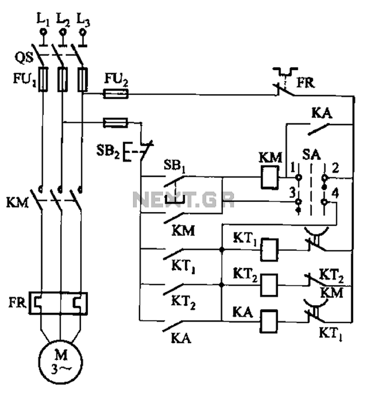
The circuit illustrated in Figure 3-78 utilizes two relays for automatic control, featuring a more complex line structure. This configuration allows for intermittent motor operation. Additionally, it can operate continuously when switch SA is positioned to the right. The circuit...