
Sound Frequency Meter Circuit

The sound frequency meter circuit is designed to provide an effective and user-friendly means of measuring audio frequencies in a compact and portable configuration. The circuit typically employs a microphone to capture sound waves, which are then converted into electrical signals. The primary function of the circuit is to measure sound frequencies, starting from a minimum input voltage level of 10 mV, ensuring it can detect a wide range of audio signals.
Key components of the circuit may include an operational amplifier (op-amp) for signal amplification, a microcontroller or frequency counter for processing the amplified signals, and a display unit, such as an LCD or LED, to present the frequency readings. The op-amp boosts the input signal from the microphone, allowing for better detection and measurement of lower frequency sounds.
The microcontroller processes the amplified signal to determine the frequency by counting the number of cycles within a specific time frame. This data is then sent to the display unit, where users can easily read the frequency measurement. Additionally, the circuit can be designed with a portable power supply, such as batteries, ensuring that it can be used in various environments without the need for a fixed power source.
In terms of construction, the circuit can be laid out on a small printed circuit board (PCB) to facilitate ease of assembly and portability. Components should be selected for their compact size and low power consumption to maintain the circuit's portability. Proper shielding and grounding techniques should also be employed to minimize noise and ensure accurate frequency measurements.
Overall, the sound frequency meter circuit is a valuable tool for applications requiring frequency analysis, such as audio engineering, music production, and sound design, making it an essential addition to the toolkit of professionals in the field.This sound frequency meter circuit is simple to build and can be constructed in a portable format. In can measure frequencies with a minimum level of 10 mV. 🔗 External reference
Related Circuits
A very useful talk-over circuit that can be utilized in radio stations, clubs, or any location where speaking over music is desired without the need for adjusting a potentiometer. The talk-over circuit is designed to automatically reduce the volume of...
Field strength meters are essential tools for individuals working with radio transmitter electronics. The following is an example of a circuit that serves this purpose. A field strength meter circuit typically consists of several key components, including an antenna, a RF...
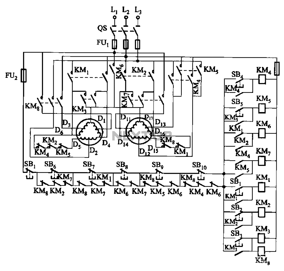
The circuit depicted in Figure 3-120 allows for the control of a motor with a capacity of less than the rated current of 5A by using an intermediate relay instead of a contactor. This circuit enables four forward running...
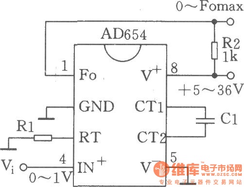
The circuit depicted is a low-cost voltage frequency converter (VFC) utilizing the AD654 component. By connecting the required components, Rl and Cl, as shown in the figure, a functional VFC application circuit can be established. The supply voltage can...
This schematic is simple and easy to construct. The integrated circuit (IC) generates all the sound effects, with the output at Pin 3 being amplified by a transistor. A 64-ohm loudspeaker can be used instead of the 56-ohm resistor...
This mini audio amplifier will test the audio stages in amplifiers such as the front end of FM bugs. You can also use it on lots of our other projects as well as the output stages of radios. It...