
Desktop Audio Switch box
The passive preamp/switchbox serves as a versatile solution for audio signal management, allowing users to switch between multiple audio sources and outputs without the need for amplification. The design utilizes double-pole double-throw (DPDT) switches to facilitate the selection of two stereo inputs and two stereo outputs. This configuration allows for seamless audio switching between devices such as a portable FM tuner and a CD player, directing the output to either a computer speaker system or a headphone amplifier.
The circuit operates on the principle of maintaining a common ground for both input and output, which is standard for most audio equipment. However, for components requiring isolated grounds, modifications to the circuit design will be necessary to accommodate those requirements.
The volume control mechanism is noteworthy, employing a modified dual 100K linear taper potentiometer, enhanced with a 22K shunt resistor to simulate an audio taper response. This adjustment results in a variable input impedance ranging from 18K to 100K ohms, which aids in ensuring consistent audio performance and reduces the potential for signal tracking issues.
Construction of the switchbox emphasizes simplicity and accessibility, making it an ideal project for beginners in electronics. The compact design allows for assembly without a printed circuit board, utilizing solid 22-gauge wire for connections. The choice of standard 3.5mm stereo mini jacks integrates well with portable audio devices, while alternatives such as RCA jacks can be considered for more traditional audio setups. The implementation of spring-loaded contacts in the jacks is recommended to enhance durability and reliability against wear over time.
Overall, this passive preamp/switchbox design exemplifies an efficient and practical approach to audio signal management, suitable for both novice and experienced electronics enthusiasts.One of the more frequently requested projects on HeadWize has been a switchbox for selecting multiple audio inputs. I built this passive preamp/switchbox several years ago to switch between two stereo sources (a portable FM tuner and portable CD player) AND two stereo outputs (a computer speaker system and a headphone amp).
It's very compact (perfect for the desktop audiophile), easy to build and uses commonly available components - including a shunt-wired linear taper pot for a volume control. The simple, low-cost design puts it within reach of beginning electronics DIYers. A passive preamp is basically a preamp that has switching functions and a volume control, but does not amplify the incoming signal. Because there is no amplification, the input signal must already be at line level, which is loosely defined in the range of 0.5V to 1.0V.
An active preamp can increase the signal strength several times before feeding it to a power amp; however, modern power amps (and headphone amps) have enough gain that they can be driven directly from the line-level source. With the exception of certain phonograph cartridges and microphones, just about every other audio component I have ever encountered has a line-level output.
Portable players may have a separate line-level output, but if not, the headphone output can be used instead - with the possible penalty of slightly more noise. Figure 1 shows the schematic for the passive preamp/switchbox (hereafter called the "switchbox"). It uses DPDT switches to toggle between the two sets of inputs and two sets of outputs. The input and output grounds are all connected to the common circuit ground. Most audio components use a common ground between the channels. The circuit must be modified to work with components that require separate grounds for each channel (see the next section for details).
The volume control is probably the most interesting feature. Since the enclosure I wanted to use was very small, I needed a mini dual pot with audio taper for a volume control. Such mini stereo pots are very hard to find in the U.S. Instead, I converted a dual 100K linear taper pot that I already had on hand to simulate an audio taper by connecting a 22K-Ohm shunt resistor from the pot's wiper to ground.
This technique produces a pot with an input impedance that varies from 18K-Ohms to 100K-Ohms, and has the additional advantage of mitigating any mistracking between sections. Construction A passive preamp/switchbox is one of the simplest electronic projects that there is. I've shown one of many possible configurations here. Despite the cramped space of the enclosure, it went together very quickly. I didn't have to use a circuit board. The only "loose" parts were the shunt resistors, which I soldered "free-floating" to the hookup wire.
The tension of the wires was adequate to hold them in place. The resistors could have been soldered directly to the pot as well. Speaking of hookup wire, I used 22 ga. solid wire throughout. Be sure to keep all wiring short and neat. I chose standard 3.5mm (1/8") stereo mini jacks for the input/output jacks, because this type of jack is common in portable players. Radio Shack sells a version of these jacks (RS 274-249). I ordered higher quality units that have spring-loaded contacts from Mouser Electronics (stock no. 161-3502). I strongly recommend the jacks with spring-loaded contacts, as they are not expensive (less than $1.00 US each) and less prone to metal fatigue, which can result in intermittent connections.
A good alternative to mini jacks would be RCA-type jacks, which are found on most non-portable audio gear. 🔗 External reference
Related Circuits
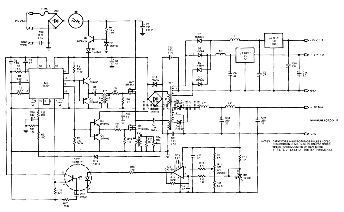
The power supply employs two VN4000A 400-V MOSPOWER FETs configured in a half-bridge arrangement. It provides outputs of +5 V at 20 A and ±15 V (or ±12 V) at 1 A. The low-current outputs utilize linear three-terminal regulators,...
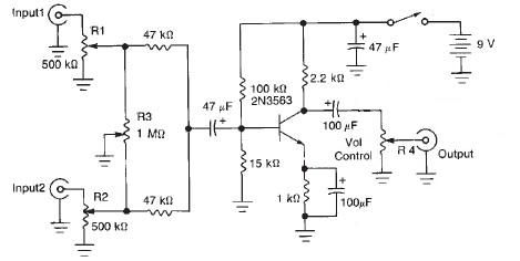
This audio mixer circuit diagram electronic project is designed using a few common electronic components. The audio mixer circuit project has two input channels. The input signal can be independently controlled using the R1 and R2 variable resistors. The...
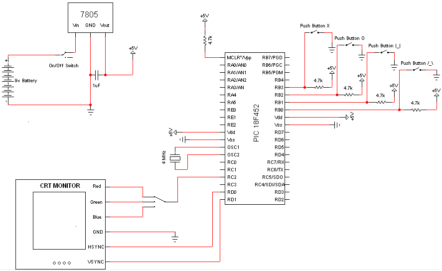
Very few electronic components are required for this project, as the PIC Microcontroller serves as the primary processing unit. The essential components include buttons, switches, and a power circuit, which are straightforward forms of input/output, facilitating an easier understanding...
To control multiple switches, it is necessary to transmit several bits via infrared (IR) transmission to indicate which key is pressed on the remote control and, consequently, which switch on the switchboard to operate. This project utilizes a commercially...
The MFOS Noise Toaster circuit comprises seven primary components: a voltage-controlled oscillator (VCO), a white noise generator, a voltage-controlled low-pass filter, a low-frequency oscillator (LFO), a simple attack-release (AR) envelope generator, a simple voltage-controlled amplifier (VCA), and a one-watt...
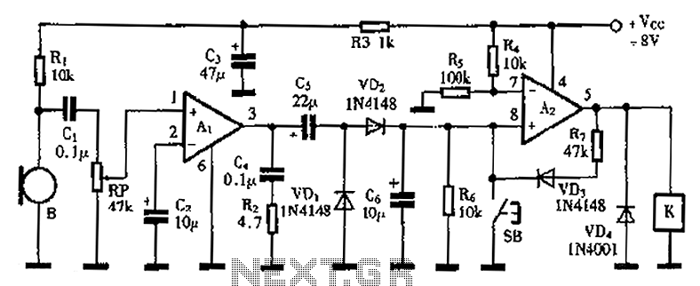
A practical voice-activated switch is presented. An A1 amplifier is connected to a conventional microphone (B) that picks up the audio control signal, which is then amplified. After amplification, the signal passes through components C5, VD1, and VD2, forming...
Warning: include(partials/cookie-banner.php): Failed to open stream: Permission denied in /var/www/html/nextgr/view-circuit.php on line 713
Warning: include(): Failed opening 'partials/cookie-banner.php' for inclusion (include_path='.:/usr/share/php') in /var/www/html/nextgr/view-circuit.php on line 713