
Detect ringing signal tone with light and sound

The described circuit is designed to detect ringing signals, commonly associated with telecommunication systems, and to provide visual and auditory alerts to the user. This circuit typically employs a combination of passive and active components to achieve its functionality.
At its core, the circuit utilizes a microphone or a capacitive sensor to pick up the ringing tone, which is usually in the range of 20 Hz to 1 kHz, depending on the system design. The output from the sensor is then fed into a signal conditioning stage, which may include filters and amplifiers to enhance the ringing tone while minimizing background noise.
Following signal conditioning, a comparator circuit is often implemented to compare the conditioned signal against a predefined threshold. When the ringing signal is detected, the comparator output transitions, triggering subsequent stages of the circuit.
For the visual indicator, an LED is commonly used. The LED is connected to a transistor that acts as a switch, allowing current to flow through the LED when the ringing signal is detected, thus illuminating the LED. This provides a clear visual indication of the ringing signal.
For the auditory component, a small piezoelectric buzzer or speaker can be integrated. The output from the comparator can also drive this buzzer, producing sound to alert the user of the detected ringing signal.
The entire circuit is designed to operate without an external power supply, which can be achieved by utilizing energy harvesting techniques or by designing the circuit to draw power from the ringing signal itself. This feature enhances the usability and versatility of the circuit, making it suitable for various applications where power availability is a concern.
Overall, this ringing signal detection circuit effectively combines light and sound indicators to provide clear alerts, ensuring that users are promptly informed of incoming calls or alerts without the need for additional power sources.The detect ringing signal tone circuit with light and sound.It is easy to use and good quality, Do not enter the power supply. Which as Detect ringing signal. 🔗 External reference
Related Circuits
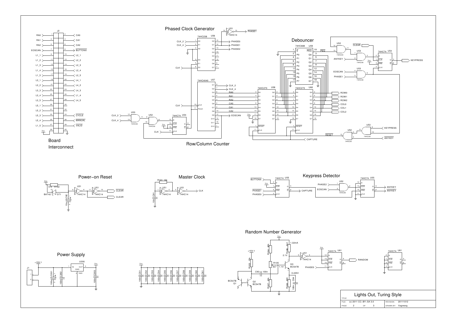
The design is based on the previous analysis of calculating the game in a circular shift register. While designing, it was realized that small extensions to the design would enable additional gameplay features, such as replay and manual input....
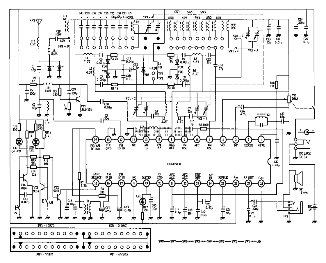
Desheng 1012 is a 12-band radio circuit diagram that covers FM, MW, SW, and TV sound frequencies. The Desheng 1012 radio circuit is designed to receive a wide range of frequencies across multiple bands, including FM (Frequency Modulation), MW...

The function of the Two Siren Sound Circuit utilizing IC 555 is divided into three parts: low frequency production, manufacturing of a shrill frequency, and low frequency output. The low frequency is generated by IC1, which is connected to...

These circuits are utilized for the detection of single-sideband (SSB) and continuous wave (CW) signals. The beat frequency oscillator (BFO) injection is generally in the range of 0.5 to 1 V rms for both circuits. The operational frequencies can...
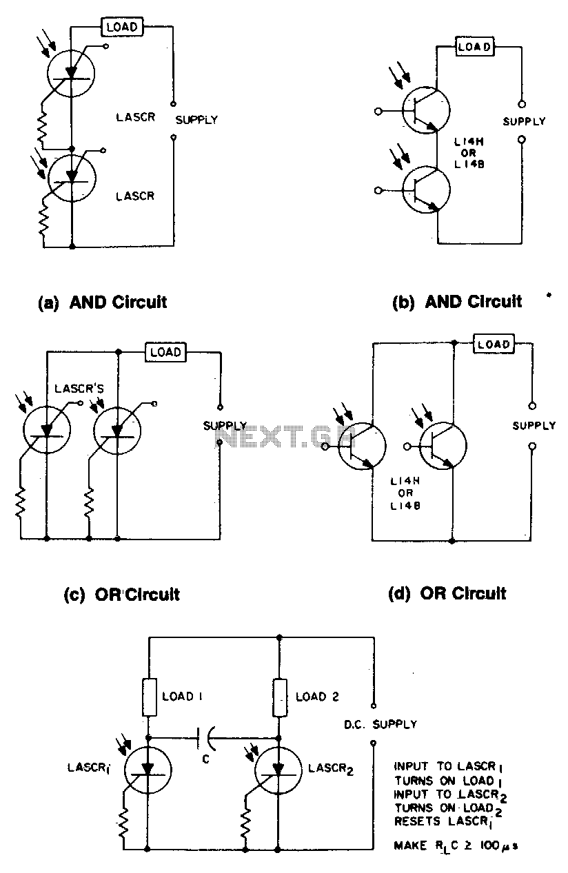
These circuits illustrate some of the common logic functions that can be implemented. The provided circuits serve as examples of fundamental logic functions utilized in digital electronics. Logic functions are the building blocks of digital systems, enabling the execution of...
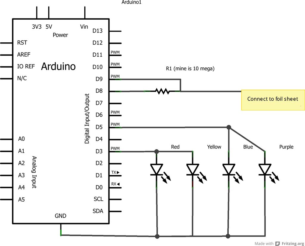
This project is an Arduino-based light control system that is ideal for beginners. It allows the fading of colors or lights by detecting hand movements nearby. The system transitions from a purple-blue hue to a fiery red-orange. The assembly...