
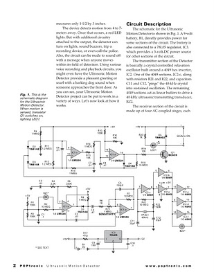
Detecting an ultrasonic beacon

An ultrasonic beacon and receiver system is integral to various applications, particularly in robotics, where precise location tracking is essential. The beacon operates by emitting ultrasonic waves at a frequency typically ranging from 35 kHz to 45 kHz. This frequency range is chosen for its effective propagation characteristics and minimal interference from ambient noise.
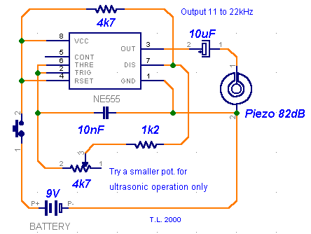
The design of the beacon can utilize several methods for generating the ultrasonic waves. A 555 timer can be configured in astable mode to produce a square wave signal, which drives an ultrasonic transducer. Alternatively, a microcontroller can be programmed to generate the desired frequency using PWM techniques, allowing for more control over the waveform characteristics. Discrete components can also be employed to create an oscillator circuit, though this may require more precise tuning.
The receiver detects the ultrasonic waves emitted by the beacon and converts them into an electrical signal. The output voltage of the receiver is directly proportional to the strength of the detected signal, which varies based on the distance from the beacon. At a distance of 4 meters, the receiver typically provides an output of over 100 mV, while at closer ranges (less than 1 meter), the output can reach up to 4 V. This significant variation in output voltage allows for effective distance measurement.
The wide emission cone of approximately 40 degrees enhances the system's ability to detect the beacon from various angles, making it suitable for dynamic environments where the orientation of the receiver may change. The output from the receiver can be interfaced with a microcontroller's ADC port, enabling the system to not only determine the direction of the incoming ultrasonic waves but also to estimate the distance to the beacon based on the output voltage.
In addition, the concept of using an MP3 file to generate the ultrasonic pulses presents an innovative approach to simplify the design. By encoding the ultrasonic frequency into an audio file and playing it through a smartphone's headphone jack, the need for a dedicated transmitter circuit can be eliminated. This method leverages existing technology to facilitate the generation of ultrasonic signals, potentially reducing costs and complexity in the overall system design.An ultrasonic beacon and a ultrasonic receiver is very similar to a beam barrier circuit, the only difference is we don`t sound an alarm when an object breaks the ultrasonic path, but instead we try to locate the ultrasonic beacon by moving the receiver. This can be useful in robotics, when we use ultrasounds to detect a target (which in fact is t he beacon itself). For the emitter (the beacon itself), all we need is an oscillator set for a 35-45KHz frequency. We can achieve this using a 555 timer, a microcontroller and PWM, or discrete components. The simple the better, even though we lack some control over the signal shape: The range is excellent, at about 4 meters, the receiver was returning more than 100mV, for the detected signal, while at less than 1 meter it was putting out 4 V. The emission cone`s angle is almost 40 degrees wide. An excellent module for robotics! These modules can be hooked up to a microcontroller`s ADC port, and will return distance dependent voltages.
So not only you can use them to spot the direction the sound is coming from, but you can also estimate the distance. The output is via the "signal" pin, which will provide approximately 0. 5V depending on the power level of the detected ultrasonic signal. i have an idea that if we craete a mp3 file which has pulses of 35 to 45khz and then connect the ultrasonic transducer directly to the phone and using head phone jack and play that mp3 file then the tx side ckt can be eliminated what say
🔗 External reference
Related Circuits
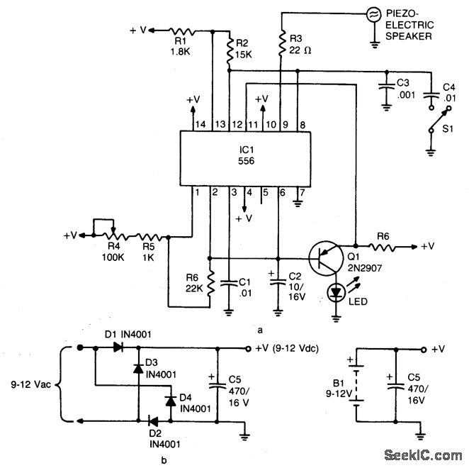
The device emits ultrasonic sound waves that sweep between 65,000 and 25,000 hertz. It is designed around a 556 dual timer, where one half operates as an astable multivibrator with an adjustable frequency of 1 to 3 Hz. The...
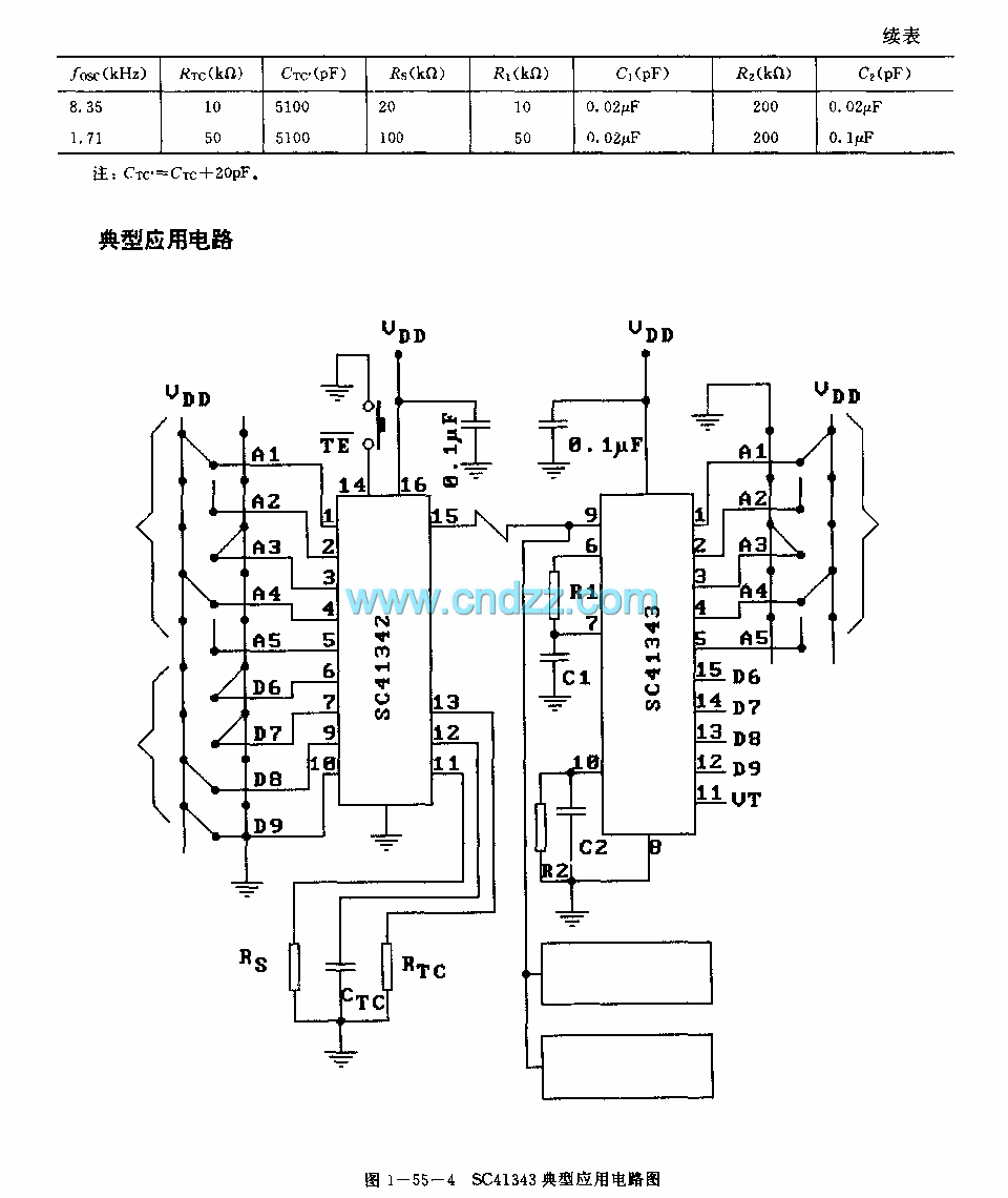
The SC41343 is designed as a type of infrared, ultrasonic, or RF remote control launch coding circuit. The internal circuit comprises a sequence generator, control logic circuit, 4-bit shift register, data extraction circuit, and latch circuit. Features include the...
The 555 timer oscillator section can be removed and replaced with a preferred microphone modulating circuit to transmit audio to a television set, requiring minimal tuning. The schematics available on Schematics Depot were sourced from the internet and are...
The circuit utilizes ultrasonic oscillations to measure the distance between two points based on the speed of sound in air. By measuring the time it takes for the ultrasonic wave to travel between these points, the distance can be...
The Diploma Final Year Project represents the culmination of the learning process, where it is essential to apply previously acquired engineering and personal skills. The assessment significantly influences decisions regarding readiness for graduation. This final year project spans an...
Many commercial pest repellers operate in the frequency range of 30 to 50 kHz. The goal was to design a more powerful audio frequency and ultrasonic sound generator suitable for training dogs. This device could potentially deter dogs from...