
ULTRASONIC PEST REPELLER

The described ultrasonic sound emitter utilizes a 556 dual timer IC, which consists of two independent timing circuits. The first half of the 556 timer is configured as an astable multivibrator, generating a low-frequency square wave output that can be adjusted between 1 Hz and 3 Hz. This output is typically used to modulate the control voltage of the second half of the timer, allowing for dynamic adjustment of the ultrasonic frequency.
The second half of the 556 timer operates as another astable multivibrator, producing a high-frequency output around 45,000 Hz. This fixed frequency serves as the primary carrier frequency for the ultrasonic sound waves. The coupling of the timing capacitor C2's voltage to the control voltage terminal (pin 11) of the second half of the 556 timer enables the modulation of the ultrasonic output frequency between 25 kHz and 65 kHz, effectively creating a sweeping sound wave.
The piezo tweeter acts as the transducer, converting the electrical signals from the 556 timer into ultrasonic sound waves. This component is specifically selected for its ability to efficiently generate high-frequency sound, making it suitable for applications requiring ultrasonic emissions, such as pest control, cleaning, or sensing technologies. The overall circuit design ensures that the output frequency can be precisely controlled and adjusted, allowing for versatility in its application.The device emits ultrasonic sound waves that sweep between 65, 000 and 25, 000 hertz. Designed around a 556 dual timer, one half operated as an astable nultivibrator with an adjustable frequency of 1 to 3 Hz. The second half is also operated as an astable multivibrator but with a fixed free running frequency around 45, 000 Hz.
The 25-65 kHz sweep is ac-complished by coupling the voltage across C2 (the timing capacitor for the first half of the 556) via Q1 to the control voltage terminal (pin 11) of the second half of the 556. The device that radiates the ultrasonic sound is a piezo tweeter. 🔗 External reference
Related Circuits
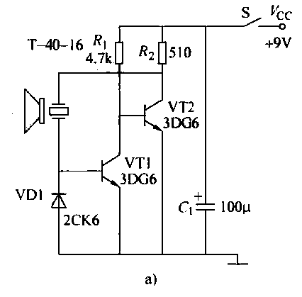
The ultrasonic transmitter circuit T-40-16, along with various discrete components, functions as a feedback sensor. The transistors VT1 and VT2 create a robust positive feedback oscillator that converts an electric signal into an ultrasonic oscillation signal, with the oscillation...
This ultrasonic anemometer is designed for the two-dimensional measurement of horizontal wind speed components and wind direction, as well as virtual temperature. Due to its high measurement rate, the device effectively captures gusts and peak values without delay. The...
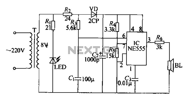
Electrical pulses are generated by the output of the first base circuit pin and sent through the R6 piezoelectric speaker, which converts the electrical pulses into ultrasonic waves. The circuit operates on a simple sweep principle, utilizing the transformer’s...
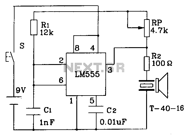
The circuit operates at a distance of 3 feet from the oscillating pulse output of a 555 timer generating a 40kHz signal, driving a T-40-16 transducer to emit ultrasonic signals at the same frequency. The circuit is powered by...
An ultrasonic sound wave can be generated using an electronic circuit. This simple electronic circuit can produce an ultrasonic wave with a frequency range of 12 kHz to... An ultrasonic sound wave generator circuit typically employs a few key components...
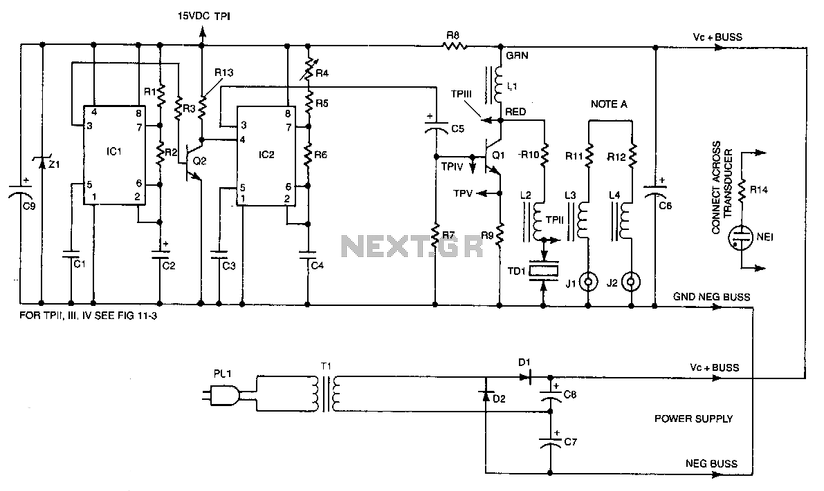
IC2 is a stable oscillator whose frequency and pulse width are determined by the values of R4, R5, R6, and C4. R4 is adjustable for precise frequency setting. The output from IC2 is at pin 3, which is capacitively...