
diac controlled led flasher

The circuit design for generating a flashing LED using AC involves several key components working together to create the desired effect. The primary components include the DB3 diac, diode D1, resistors R1 and R2, capacitor C1, and the LED itself.
The diode D1 plays a crucial role in converting the incoming AC voltage into a high voltage DC. It ensures that the current flows in a single direction, providing the necessary voltage for the diac to operate. The rectified DC voltage is then fed into the diac, which remains non-conductive until the voltage reaches its breakdown threshold.
Resistor R1 is essential for controlling the voltage applied to the diac, preventing it from exceeding safe levels while allowing enough current to charge capacitor C1. The value of R1 will influence the charging time of C1, thus affecting the flash rate of the LED. Resistor R2 serves to limit the current flowing through the LED to a maximum of 30 mA, protecting the LED from potential damage due to excessive current.
Capacitor C1 is the component that dictates the flashing rate of the LED. As it charges, it increases the voltage across the diac until the breakdown threshold is reached, at which point the diac conducts and allows current to flow through the LED, causing it to light up. Once C1 discharges, the voltage across the diac drops below the threshold, turning off the LED. This cycle repeats, producing the flashing effect.
It is important to select appropriate values for the components to achieve the desired performance. The capacitance of C1 should be chosen based on the desired flash rate, with higher capacitance resulting in slower flashing. If the circuit does not function as intended, adjustments to R1 may be necessary, ensuring that the wattage rating is sufficient for the new value.
Due to the high voltage AC connection, significant caution must be exercised. The circuit should be housed in a protective enclosure to prevent accidental contact with live components, and proper safety protocols should be followed to mitigate the risk of electric shock.This is probably the simplest idea to generate flashing light from an LED using AC. The circuit is relatively the simple way of flashing one or more LEDs from a high voltage DC obtained from Mains. This can be used as a Mains indicator or Mock flasher. The circuit uses a diac for the alternate switching of LED. The diac is usually used in pulse ge nerator circuits to trigger SCR and Triac. If a low voltage passes through a diac, it simply behaves like an open circuit and only very low current passes through it. But if the voltage increases to the breakdown threshold of the diac, it will pass heavy current. Usually 35 volt DC is required to attain the threshold level of diac. Unlike SCR, diac conduct in both the directions. In the circuit, a commonly available DB3 diac is used. Diode D1 rectifies AC and generates a high volt DC. Resistor R1 safely controls the DC to operate diac and LED. Normally LED will be OFF. When the capacitor charges fully, diac gets the threshold voltage and fires. This provides current to LED and it lights. Resistor R2 makes the LED current to a safer value of 30 mA. When the diac conducts, C1 discharges and again the breakdown voltage of diac decreases and LED turns off.
Thus the charging/discharging cycles of C1 makes the LED flashing. The value of C1 determines the flash rate. Higher values give slow flash rate and vice versa. If the threshold level of diac is not obtained using the given value of R1, reduce it to 10K, but its wattage should be increased to 5 watts. Caution: The circuit is directly connected to high volt AC and there is no galvanic isolation. Take utmost care while handling the circuit. Enclose it in a shock proof case. Do not touch any points when it is connected to Mains. 🔗 External reference
Related Circuits

Power Integrations' DER322 reference design employs the LinkSwitch-PL family of LNK460VG devices. This design represents the industry's first alternative 100W A19 incandescent LED driver utilizing a single-layer PCB. It is characterized by low cost, minimal component count, and compact...
This 1.5 volt LED flasher runs more than a year on a single 'D' cell and alternately flashes 2 LEDs at about a 1 second rate. The circuit employs a 74HC14 CMOS hex inverter that will operate at very...
To create a battery-operated LED lamp, it is preferable to utilize a cluster of low-power discrete LED arrays instead of a single high-power LED. This configuration allows for scattered light production, significantly reducing irritation or potential damage to the...

This ultra-bright white LED lamp operates on 230V AC with minimal power consumption. It is suitable for illuminating VU meters, SWR meters, and similar applications. The cost of ultra-bright LEDs available in the market ranges from Rs 8 to...
The question sometimes comes up of how to cascade 4017 decade counters for more than 10 sequential stages. The LED sequencer below shows a possible solution using a few extra parts. When power is applied, the 15K resistor and...
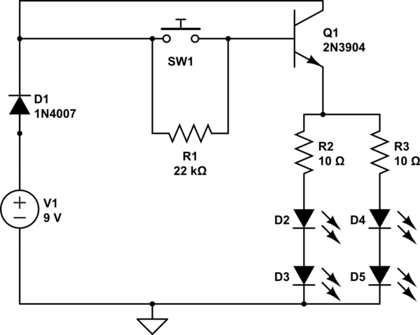
A circuit has been constructed that functions unexpectedly. The circuit utilizes red 5mm LEDs as diodes, a 3904 NPN transistor, and resistors as indicated in the schematic. Logically, pressing the push button normally open (PBNO) should result in the...