
Differentiator Op Amp Circuit

The differentiator circuit utilizes an operational amplifier to produce an output voltage that is proportional to the rate of change of the input voltage. This characteristic is particularly useful in applications requiring the detection of rapid changes in signal levels, such as in signal processing and control systems.
In a typical differentiator circuit, the input signal is applied to the inverting terminal of the op-amp through a capacitor (C1), while a resistor (R1) connects the output to the inverting input. The non-inverting terminal is grounded. The output voltage (Vout) can be expressed as Vout = -R1 * C1 * (dVin/dt), where Vin is the input voltage and dVin/dt is the derivative of the input voltage with respect to time.
The component values, R1 and C1, must be carefully selected to ensure the desired frequency response and stability of the circuit. The feedback resistor (RF) and capacitor (CF) may also be included to enhance performance, particularly in high-frequency applications, by compensating for phase shifts and improving bandwidth.
It is important to note that the differentiator circuit can amplify high-frequency noise, which may lead to instability. Therefore, appropriate filtering techniques or frequency limitations should be implemented to mitigate these effects. The circuit may also need to be designed with considerations for power supply voltages, op-amp characteristics, and load conditions to ensure reliable operation across the intended application range.
In summary, the differentiator circuit is a versatile tool in electronic design, providing essential functionality for applications that require responsive signal processing and rapid change detection. Proper design and component selection are critical to achieving optimal performance.Differentiator circuit is application circuit from playable mathematics formula (influenced) from capacitor activity. The circuit like at picture under this with simple circuit from differentiator. To get formula differentiator, the sequence is as following: Ic = Ib + If and during value Ib = 0 hence Ic = If difference from inverting input and non
-inverting input (v1 and v2) be the null and voltage amplification is very big. At the application of differentiator circuit this op-amp there are a few changes that is addition of prisoner and capacitor which the function input signal filter to. Like seen at picture following is differentiator circuit intended. If, when input signal exceeds frequency fa hence result of output would equal to result of input, alias function of the differentiator circuit shall no longer again but as ordinary.
While to drawing 226 usually applied for application integrated circuit with other application. Condition calculation value R1, C1, RF, CF is as according to condition that is: 🔗 External reference
Related Circuits
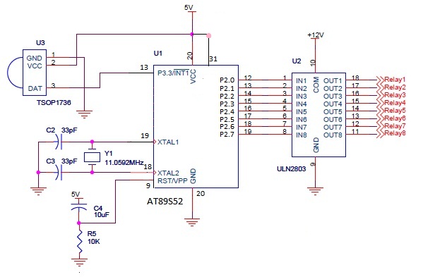
The infrared (IR) circuit is designed to control multiple devices using a TV remote. Unlike standard circuits that can typically switch only one device, this circuit allows for the operation of different devices with the same remote by utilizing...
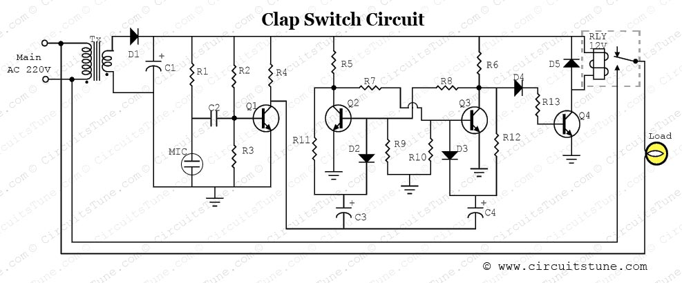
This is a simple electronic circuit for a clap switch project. It is suitable for beginner electronics learners who enjoy experimenting with new projects. The circuit can turn on or off a 220V electronic device, such as a fan...
This circuit consists of two main components: a battery charger that provides a fixed output voltage of 5V DC, and a regulated power supply that allows for an adjustable output voltage ranging from 2 to 9 volts. The circuit design...

This lie detector circuit provides two readings: one for difficult questions and another for the subject's general emotional state. Two flexible, uninsulated wires wrapped around the fingers or wrist can serve as electrodes. Each change in resistance, and consequently...
The 1C foot VIII developed a training device, utilizing the trigger terminal CI for a positive input pulse. It concludes by providing a quotient output level. The system involves a commercial electric circuit featuring a buck converter, which limits...
A straightforward 4-channel video amplifier electronic circuit can be constructed using the NJM2582 integrated circuit, which is suitable for video applications with a SCART connector. The design of this circuit is uncomplicated and requires only a few external electronic...