
digital alarm clock

LCD (Liquid Crystal Display) interfacing is a common task in embedded systems, particularly in digital clocks and other display applications. When addressing issues with LCDs, it is essential to focus on the timing and delay routines used in the code. Delay routines can significantly affect the performance of the LCD, leading to various display anomalies if not properly implemented.
Before proceeding with more complex applications like a digital clock, it is advisable to ensure that the LCD is interfaced correctly with the microcontroller. This involves verifying connections such as data lines, control lines (RS, RW, EN), and power supply (VCC and GND). The use of a systematic, step-by-step approach can help identify and rectify potential issues early in the development process.
For further clarification of hardware functionality, it is beneficial to start with a simple LED blinking program. This program can serve as a basic test to confirm that the microcontroller is functioning correctly and that the hardware setup is sound. Once the LED program operates without issues, the focus can shift to integrating the LCD.
When working in 4-bit mode, it is crucial to ensure that the data lines are connected correctly and that the timing specifications outlined in the LCD datasheet are adhered to. Logic contention errors, which can occur due to incorrect wiring or timing issues, can result in the LCD displaying garbled characters or failing to initialize. Common mistakes include shorting VCC and ground or improperly configuring the data pins. It is essential to double-check all connections and ensure that the control signals are correctly timed to avoid these problems.
In summary, a thorough understanding of both the hardware connections and the software routines is vital for successful LCD integration. Following the recommended practices and utilizing available resources, such as tutorials, can greatly enhance the likelihood of a successful implementation.Most of the LCD issues are due to Delay routines only. First try to interface LCD properly then try for your digital clock. Step by step approach is important. You may refer to LCD tutorial which is in tutorial section. code is ok i check it on Proteus it is working well here is the file u can see it firstly try a led blinking program that clearthe hardware doubt still this code can `t tell us that is hardware issue of software Logic contentions detected often come when lcd is driving in 4 bit mode or there is a logically wrong connections let say u joint a vcc and ground then this error come also 🔗 External reference
Related Circuits
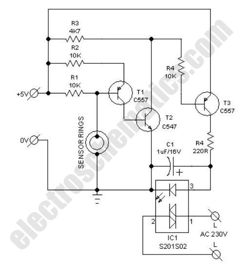
This compact water sensor alarm circuit emits a loud warning sound when a humidity sensor detects the presence of water. The circuit utilizes the low-power comparator LM1801 from National Semiconductor. A fixed reference voltage for the integrated circuit is...
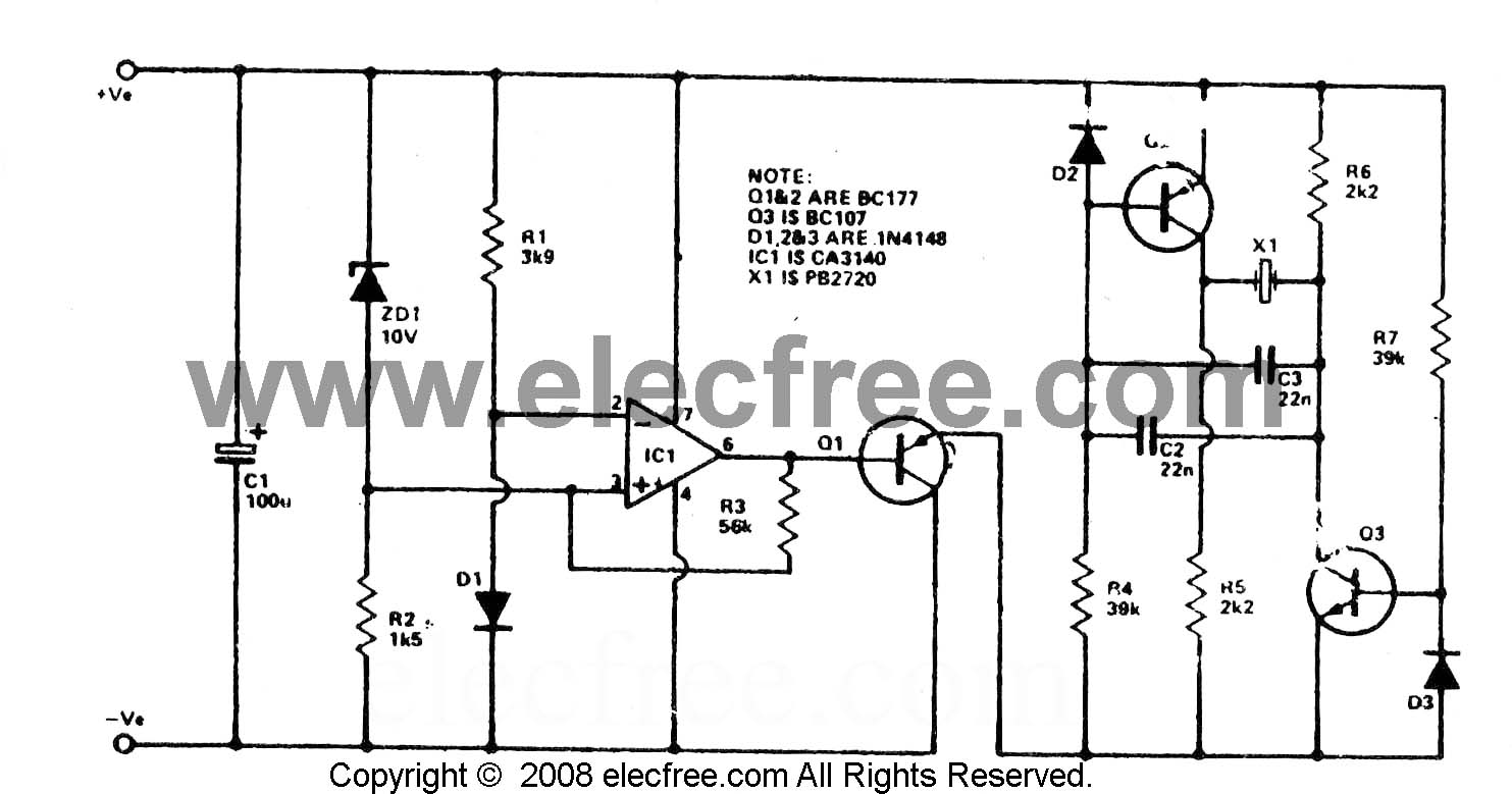
To check the battery in a car, an easy circuit utilizing the IC CA3140 and a transistor is employed. The voltage level of an automobile battery is influenced by many factors, and if it is high... The circuit for checking...
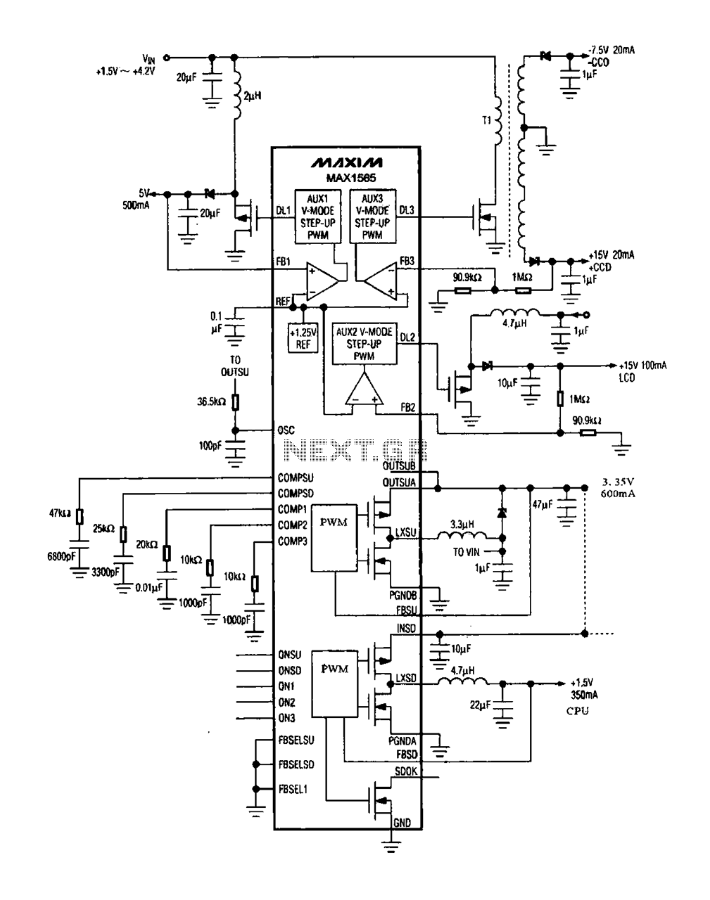
The digital camera power supply utilizes the MAX1565 chip, which features a five-channel power supply configuration. The chip generates various signal widths and control circuits tailored to meet the DC voltage and current requirements of the digital camera. The...
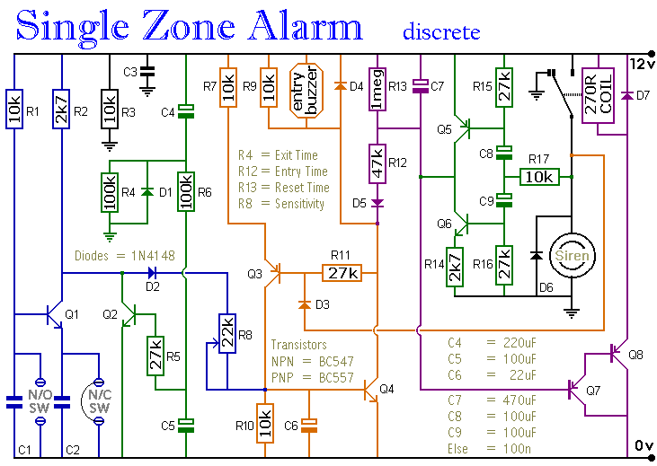
A single zone alarm circuit with entry and exit delay and other facilities. The circuit features automatic exit and entry delays, timed bell cut-off and system reset. It has provision for normally open and normally closed switches and will...
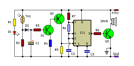
This is a small and simple unit that can be utilized for home security purposes. In this fire alarm circuit, a thermistor functions as the heat sensor. When the temperature increases... The fire alarm circuit described utilizes a thermistor, a...
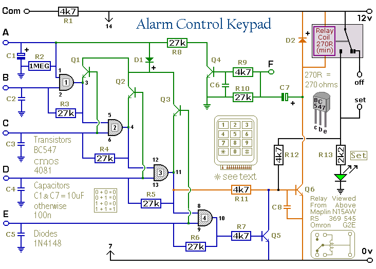
This keypad is designed for use with the Modular Burglar Alarm system, although it can be applied in various other contexts. Inputting the first four digits of a selected five-digit code will activate the relay, while entering the complete...