
Digital Calender Circuit

The digital calendar circuit is designed to provide a clear and efficient way to display time-related information. The AT89C2051 microcontroller serves as the core of the system, executing the programmed instructions to control the various components. The microcontroller interfaces with the LED displays, driving them to illuminate the appropriate indicators for the current date, day, and month.
The circuit architecture typically includes a power supply section that can accommodate both AC and DC inputs, ensuring compatibility with various power sources. The battery backup system is crucial for maintaining functionality during power interruptions, allowing the calendar to retain its settings and continue displaying the correct information.
The LED indicators are arranged in a user-friendly manner, with 31 individual LEDs representing each day of the month, 12 LEDs for the months of the year, and 7 LEDs to indicate the days of the week. This arrangement allows users to easily visualize the current date and time information at a glance.
In terms of programming, the microcontroller's ROM is preloaded with the necessary algorithms to manage the timekeeping functions, including leap year calculations and month length variations. The microcontroller periodically updates the display based on an internal clock, ensuring accurate timekeeping.
The schematic drawing accompanying the circuit description would typically illustrate the connections between the microcontroller, the LED indicators, the power supply, and any additional components such as resistors, capacitors, and potentially a real-time clock (RTC) module for enhanced accuracy. The design emphasizes simplicity and reliability, making it suitable for educational projects or practical applications in timekeeping devices.Here is calendar digital circuit. this circuit using Microcontroller is an advanced digital calendar, which displays the Date, Day, Month over the LED display. All the above systems are controlled by the Microcontroller. It has an 8 bit Microcontroller which runs on the Program embedded on its ROM. Separate LED`s are provided for the date, day, a nd month. The system has an battery backup so that it can run over all the time even during the power failure. Totally there are 31 LED`s for indicating the date and 12 LED`s for indicating the Month and 7 LED`s to indicate the day. In our project we are using the popular 8 bit microcontroller AT89C2051. It is a 20 pin microcontroller. Here is a schematic drawing: 🔗 External reference
Related Circuits
When this thermometer is utilized in a room environment, it operates intermittently, maintaining this operational state within the temperature measurement circuit due to the stable internal temperature. The astable multiresonance oscillator is composed of transistors VT1 and VT2, forming...
Ensure to verify all connections utilizing the circuit diagram and breadboard schematic available for download from the provided links. This resource can assist during the assembly process. To create a reliable electronic circuit, it is essential to meticulously verify all...
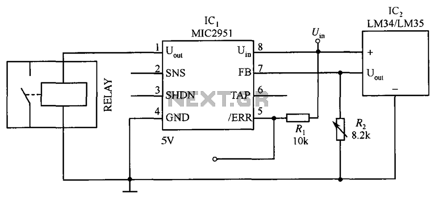
The circuit depicted in the figure utilizes a thermal protection system featuring the MIC2951 component. The temperature threshold can be adjusted by modifying resistor R2. The thermal protection circuit employing the MIC2951 is designed to monitor and regulate temperature within...
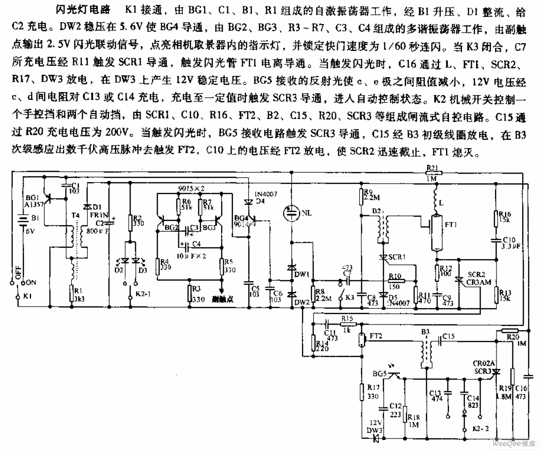
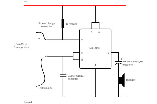
The camera flashlight circuit activates when switch K1 is engaged. This triggers a self-oscillating circuit consisting of BG1, capacitor C1, battery B1, and resistor R1. Once operational, the circuit boosts the voltage through B1 and rectifies it using diode...

This is a circuit known as a Wien bridge oscillator circuit. The circuit features both positive and negative feedback loops and operates under the control of an operational amplifier (op-amp). The oscillation frequency is determined by the RC time...
A series of shunts and multipliers selected by a switch can be utilized in conjunction with a single basic meter to create a multirange instrument, commonly referred to as a multimeter. This device is capable of measuring voltage, current,...