
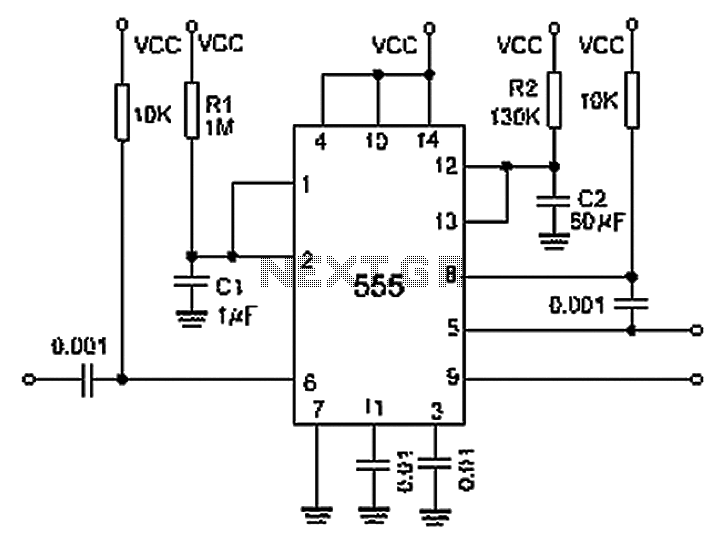
Time delay circuit using a UJT

The time delay circuit based on a UJT operates by charging a capacitor through a resistor network, where the UJT serves as a switching element. The circuit primarily consists of a UJT, a timing capacitor, a resistor, and a potentiometer for fine-tuning the delay.
When power is applied, the capacitor begins to charge through the resistor, and the time it takes to reach the UJT's triggering voltage determines the delay. The 10 MΩ potentiometer allows for a wide range of resistance values, enabling precise control over the charge time and, consequently, the delay duration.
The capacitor voltage increases gradually until it reaches the peak point of the UJT's characteristic curve, at which point the UJT turns on, discharging the capacitor and triggering the connected load. This action can be utilized in various applications, such as timers, delay switches, or pulse generators.
The circuit's design should include proper biasing for the UJT to ensure stable operation, and considerations for component tolerances are necessary to maintain the desired timing accuracy. Additionally, the selection of the capacitor value and the resistor in conjunction with the potentiometer will influence the overall timing range and performance of the circuit.
For optimal functionality, it is also advisable to incorporate bypass capacitors to filter out any noise that may affect the timing accuracy, and to ensure that the circuit is housed in a suitable enclosure to prevent external interference.Time delay circuit using a UJT. Maximum time delay is set by the 10M pot. Time delay can be set from less than a second to approximately 2. 5 minutes (courtesy Motorola Semiconductor Products Inc. ). 🔗 External reference
Related Circuits
The technical parameters of high-speed optocouplers include a rise time (t1) of less than or equal to 300 ns, a circuit transfer ratio (CTR) of 50%, an isolation voltage (VSO) of at least 15,000 V, and an output transistor...
Circuit designed to alleviate concerns related to high frequency utilizes a ready-made module, specifically an Aurel audio FM transmitter. This compact circuit board, measuring 2 cm by 4 cm, supports a modulation frequency track and delivers an RF power...
It is essentially an all-pass filter with two additional components: a capacitor and a resistor, which produces percussion sounds. A schematic of the unmodified all-pass filter circuit, a waveform captured via Audacity, and a short audio sample featuring a...
A 0.001 F coupling capacitor connects the output of the first half of a 556 timer to the input of the second half, providing an individual delay that equals the total delay. The 6-foot ground can immediately activate the...
This device is designed to maintain a deep cycle battery using energy harvested from a solar panel. It functions as a combination of a digital clock timer and a solar panel charge controller. Component: .. This circuit serves the dual...
This is a digital dice circuit that uses the PIC16C84. The digital dice circuit utilizing the PIC16C84 microcontroller is designed to simulate the random rolling of a standard six-sided die. The circuit operates by generating a random number between 1...