The stock ATS-3A transceiver has been modified to transmit BPSK31 signals, specifically "cq ok1iak." The firmware was altered to enable serial line control through the DASH paddle pin while in straight key mode, which disables the paddle in remote control mode. To allow both remote control and paddle operation, hardware modifications to the ATS-3A are necessary. The BPSK31 envelope can only be shaped by toggling the transmitter on and off. Although the envelope does not achieve a raised cosine shape, the signal width remains comparable to that of CW, with sidelobes expected to be minimal at QRP levels. Testing with various PSK31 programs, including MIXW32, MultiPSK, DigiPan, and PocketDigi, yielded satisfactory results, although WinPSK experienced occasional dropouts. A screenshot of the BPSK31 signal was captured on a RadioShack DX-398, where the receiver may have been overloaded. The ATS can generate RTTY or MFSK16 modulation patterns effectively. While Olivia modulation utilizes symbol shaping, hard keying, as seen in MFSK16, is anticipated to perform adequately. The serial line protocol operates at 1200Bd asynchronous with 8 bits, 1 start, and 1 stop bit. Targeting handheld computers, the serial stream is created by a sound card in the 202 format and converted to 0/3.3V digital levels using an external FSK decoder. The two tones utilized are 1200Hz for mark and 2200Hz for space, with the tones represented as 0V for space and 3.3V for mark. Currently, ATS support has not been implemented into PocketDigi; however, a simple C++ application has been developed to generate WAV sound files with various commands. These WAV files can be played on PCs, Pocket PCs, or mobile devices. The modified ATS-3A firmware source or binary, along with the Windows WAV generator source or binary and command WAV files, can be provided for experimentation, contingent upon the ability to flash the firmware. For guidance on flashing ATS firmware, refer to qrpradio.com/ats3.html. Efforts to develop PocketDigi support are underway, with hopes of achieving PSK31 QSOs during visits to family, as antenna options are limited in the current living situation. Additionally, a tone decoder schematic has been built, focusing on the decoding part as shown in net/yo5ofh/projects/xrmodem.gif. The Exar XR2211 analog FSK demodulator chip is affordable and readily available. The capacitor value C5 has been reduced to 4.7nF, and pins 6 and 7 have been connected to enable muting in the absence of an input signal. When there is no input, the DASH pin remains low, and the ATS-3A initializes in straight key/remote control mode. Two red LEDs are connected to pin 7 to ensure the maximum output voltage reaches 3.3V. The XR2211 decoder's analog nature makes it sensitive to component tolerances, which can complicate tuning. A tone generator is useful, with several free PC sound card tone generators available online. An LED connected to pin 5 indicates phase loop lock, aiding in tuning the oscillator within the appropriate frequency range. Another LED on pin 6 indicates the decoded tone, with the transition frequency calculated as the geometric average of the two tones, approximately 1625Hz. A prototype of the tone decoder is enclosed in a black plastic box, which is only partially filled, suggesting that a smaller SMD version is feasible. The tone decoder draws approximately 4mA. A MAX232 level converter is used on a small breadboard above the plastic box to monitor the FSK decoder. Alternatives to the XR2211 include MX/FX614 chips, which, while more expensive and harder to acquire, consume only 1mA at 3.3V and do not require tuning. A daughterboard mounted opposite the band filter is expected to fit inside an Altoids tin. Another decoding approach could involve interpreting pulses instead of tones.I have managed to let the stock ATS-3A transceiver transmit nice BPSK31 "cq ok1iak". The firmware of ATS-3A was modified to allow serial line control, which is performed over the DASH paddle pin in straight key mode. That means paddle will not work if in remote control mode. To enable both remote control and paddle woul d need hardware modification of the stock ATS-3A. The only way to shape the BPSK31 envelope on a stock ATS is to key the transmitter on/off. The envelope is far from raised cosine, but the signal is not wider than of CW and the sidelobes will be hopefuly negligible at QRP levels. I tested common windows PSK31 programs how they will cope with that non ideal envelope. MIXW32, MultiPSK, DigiPan and PocketDigi worked well, WinPSK had occasional drop outs. Here is the screenshot of BPSK31 signal received on RadioShack DX-398. On the lower part of the screenshot the receiver may have been overloaded. RTTY or MFSK16 modulation patterns may be generated by ATS perfectly. Olivia uses symbol shaping, but I bet hard keying like in the case of MFSK16 will work good enough. The serial line hardware protocol is 1200Bd asynchronous, 8bit, 1 start, one stop bit. Because I am targeting mainly handheld computers, the serial stream is generated by a sound card in the 202 format and transformed to the 0/3.
3V digital levels by an external FSK decoder. The two tones are 1200Hz mark and 2200Hz space. The tones are converted to 0V for space and 3. 3V for mark. I did not implement ATS support into PocketDigi yet, I only wrote a simple C+ application to generate WAV sound files with various commands. Those WAV files may be played on a PC, Pocket PC or even on a mobile phone or MP3 player. I will be happy to provide modified ATS-3A firmware source or binary, the windows wav generator source or binary or command wav files to anyone wanting to experiment.
The prerequisity is to be able to flash the firmware. For introduction to ATS firmware flashing look at qrpradio. com/ats3. html I will work on PocketDigi support now and I hope to make some PSK31 QSOs when I visit my parents` house. I do not have any antenna possibility at my appartment. BTW I will try to pursue some student at my alma mater - the Now to the tone decoder. I built only decoding part of the following schematic net/yo5ofh/ projects/ xrmodem. gif. The analog FSK demodulator chip from Exar XR2211 is readily available and cheap. The value of C5 is too big, I decreased it to 4N7. I connected pins 6 and 7 to provide muting if there is no signal on the line. Without input signal the DASH pin is low and ATS-3A is configured to straight key / remote control on startup.
I connected two red LED diodes to pin 7 to pull the maximum output voltage to 3. 3V. The XR2211 decoder is analog, which means it is sensitive to component tolerances. I do not have much experience with analog circuits and I had hard time to tune it. Tone generator is very handy, there is a bunch of free PC sound card tone generators on the internet. Connect LED to pin 5 to indicate phase loop lock. This will help to avoid tuning the oscillator above space or below mark tones. Put LED on pin 6 to indicate decoded tone. The transition frequency is geometric average of the two tones, sqrt(1200*2200) =1625Hz. This is a picture of my prototype. The black plastic box is half empty and the tone decoder will be much smaller if made in SMD. The tone decoder sources cca 4mA. The small bread board above the plastic box is a MAX232 level convertor to monitor the FSK decoder. There are following alternatives to the XR2211 FSK decoder. MX/FX614 chips are expensive (about $10) and hard to get, but they consume only 1mA at 3. 3V. They are digital, no tuning is nescessary. Daugter board mounted on the opposite to the band filter will fit inside the altoids tin for sure. Other possibility would be to decode pulses instead of tones, which would 🔗 External reference
The receiver circuit and display module will receive the high-frequency AC power cord and decode it to provide actual temperature readings using digital IC No. CD4553 (Three-digit BCD Counter IC) and IC CD4511 (BCD-to-7-Segment Latch/Decoder/Driver IC). The frequency pulses...
A pH meter is a precise voltmeter that measures the generated voltage of pH electrodes. The demand for such a meter is significant.
A pH meter operates by utilizing a combination of a glass electrode and a reference electrode. The...
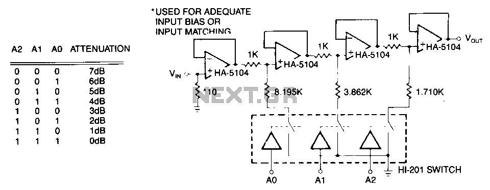
The first stage is a simple buffer used to isolate the signal source from the following attenuator stages. Each subsequent stage is preceded by a voltage divider formed by two resistors and a CMOS switch. When the CMOS switch...
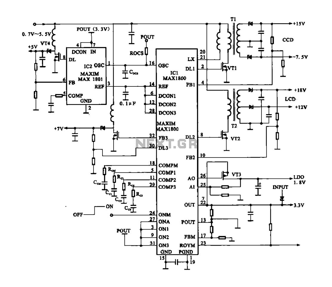
Digital Cameras - DV machine power supply circuit. This circuit utilizes the MAX1800 chip to manage the power supply for digital cameras and DV machines. Digital cameras are typically battery-operated and require low voltages ranging from 0.7 to 5.5...
This circuit is a digital voltmeter diagram featuring an LED display. It is designed for measuring the output voltage of a DC power supply. The voltmeter incorporates a 3.5-digit LED display along with a negative voltage indicator. It is...
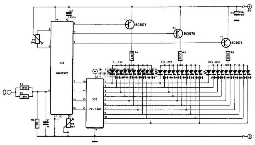
The voltage to be measured is digitized in an analog-to-digital (A/D) converter and then displayed in three decimal digits. The display consists of three groups of 10 LEDs. The meter can only be used for measuring direct voltages. The...
We use cookies to enhance your experience, analyze traffic, and serve personalized ads.
By clicking "Accept", you agree to our use of cookies.
Learn more