
Digital Clock Timer schematic

The described clock timer circuit integrates a PIC16F628 microcontroller, which serves as the central processing unit. The microcontroller interfaces with a 32.768 kHz watch crystal oscillator, providing the necessary timing signal for accurate clock operation. The circuit is designed to display time in a 3.5-digit format, alongside additional features such as a calendar, alarm, and daylight savings adjustments.
The timer output can be configured to operate between 1 to 59 minutes, with manual activation and deactivation capabilities. A correction feature is incorporated to adjust the oscillator's frequency by adding an additional second at specified intervals, ensuring long-term accuracy. This is facilitated by a 24pF capacitor connected to the oscillator, which allows for fine-tuning of the frequency.
The user interface consists of several switches: RA0 for displaying the current time, RA1 for advancing through various display modes (alarm, calendar, etc.), and RA2/RA3 for adjusting the hour and minute settings during setup. The RA5 switch determines the operational mode, with a position for setup and another for normal operation.
The alarm functionality is controlled through an interrupt routine, which has been noted to have a bug related to the zero-minute setting. A modification to the program code has been suggested to ensure the alarm operates correctly across all minute settings. The display sequence includes time, alarm, calendar, weekday, AM/PM settings for both the alarm and current time, and the daylight savings status.
The daylight savings feature allows the user to enable or disable adjustments based on the current time of year, with settings indicating whether daylight savings is active or not. The year and correction settings provide additional functionality to ensure the clock remains accurate, with the correction adjusting the timing based on the user's specific oscillator characteristics.
Overall, this clock timer circuit is a versatile and programmable solution for timekeeping, integrating various features to enhance user experience and accuracy.This clock timer uses a PIC16F628 microcontroller to display 3 and 1/2 digit time and control an external load. The clock includes a calendar with leap year and optional daylight savings adjustments. The timer output can be set from 1 to 59 minutes and manually switched on and off. The clock also has a correction feature that allows an additional second to be added every so many hours to compensate for a slightly slow running oscillator.
The oscillator uses a common 32.768 KHz watch crystal and the frequency can be adjusted slightly with the 24pF capacitor on the right side of the crystal. There is a bug in this program that prevents the alarm from working if the minutes are set to zero. So, an alarm setting of 8:59 or 6:01 will work but 6:00 will not. The bug can be fixed by adding a program line to call the alarm routine after the hours are incremented. Current listing in the interrupt section is: call Alarm movlw d'60' xorwf MINUTES,0 btfss STATUS,2 ; Check for 60 minutes goto Done ; Jump out if not 60 clrf MINUTES incf HOURS,f New listing should be: call Alarm movlw d'60' xorwf MINUTES,0 btfss STATUS,2 ; Check for 60 minutes goto Done ; Jump out if not 60 clrf MINUTES incf HOURS,f call Alarm ; New line added here On bootup, the display should read 2:56 AM and other data can be displayed by toggling the advance switch (D).
Each time the (D) switch is closed and opened, the display will advance to the next data. The order of displayed data and bootup values is as follows: Time --------------------------------------------- (2:56) Alarm --------------------------------------------- (6:30) Calendar --------------------------------------------- (3:07) Weekday (Sunday=1), Seconds ---------------------------- (1:Seconds) AM/PM (Alarm) (AM=0/PM=1), Timer Duration ------------- (0:45) AM/PM (Time) (AM=0/PM=1), Daylight Savings Disabled -- (0:00) Year (1 to 4) , Error Correction ---------- (2:18) There are 7 displays that advance each time the 'D' switch is toggled. To make adjustments, set the RA5 switch to the "B" position and then toggle the E and F switches to advance the data in the hours or minutes digits.
Then toggle the "D" switch to move to the next data. After the 7th display, it will go back to the top and display the current time. Or, just press the time switch 'C' to get to the top at anytime. When done setting everything up, set the RA5 switch to the "A" position so the data cannot be accendentally changed. You can still view everything with the "D" advance key, but the E an F switches will just turn on or off the alarm at RB7.
I use it with an external transistor to switch on and off a radio. The 'Daylight savings' setting (in the 6th display in the minutes digits) is used to enable daylight savings time adjustments, one hour ahead on the 2nd sunday in March, and one hour behind on the first sunday in November. The entry will be either 0, 1, or 3. 0 = Daylight savings time disabled (default). 1 = Savings time enabled and current time is standard time. 3 = Savings time enabled and current time is daylight savings time. The last 2 entries on the list (Year and Correction) is for the current year (1 to 4) (4 = Leapyear) so today's setting (2006) will be 2 since leapyear will be on year 4 which is 2 years from now.
The correction setting will add a second every so many hours for fine adjustment to the oscillator frequency. My setting is 18 which adds a second every 18 hours. It's pretty accurate and only loses 3 seconds a month. You probably want to run it for a couple weeks to figure out what correction is needed for the crystal you have.
Switch functions: RA0 (C switch) = Display Time RA1 (D switch) = Advance to next data (alarm, calendar, etc) RA2, RA3 (E and F switch) = Advance hours and minutes (in setup mode). RA2, RA3 (E and F switch) = Toggle alarm output on/off (in run mode) RA5 in the 'B' position (open) = Setup Mode
🔗 External reference
Related Circuits
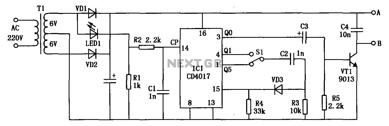
The electromagnetic RBI timer features a simple structure, is cost-effective, and is commonly utilized in high school physics experiments. However, a significant drawback of the electromagnetic RBI timer is the substantial errors it produces during experiments. This issue arises...
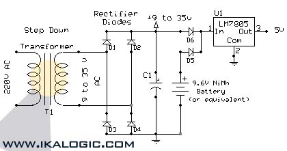
This circuit supplies electric power from a backup battery when AC power is interrupted, ensuring a stable 5V power supply for sensitive devices such as microcontrollers and logic circuits. The capacitor C1 should have a capacitance greater than 220...
This circuit turns off an amplifier or any other device when a low-level audio signal fed to its input is absent for at least 15 minutes. Pressing P1 switches the device on, supplying power to any appliance connected to...
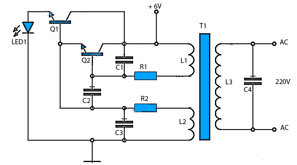
The circuit schematic presented is a voltage inverter circuit that converts a 6-volt DC input into a 220-volt AC output. It is designed to deliver a maximum output power of 30 watts and operates with a low input current....
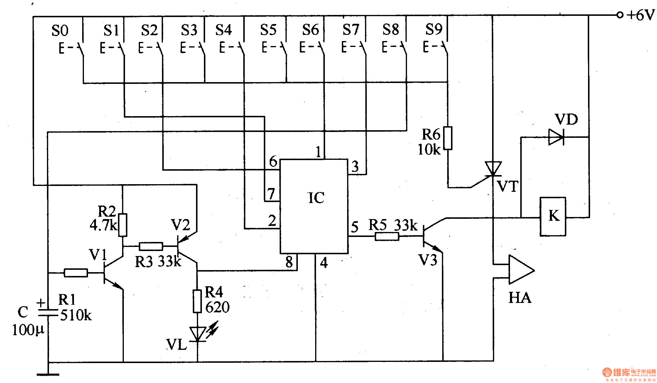
The digital lock circuit consists of a timing trigger circuit, a trick lock circuit, a sound and alarm circuit, and a control implementation circuit, as illustrated in Figure 3-101. The timing trigger circuit is made up of transistors V1...
The digital lock shown below uses 4 common logic ICs to allow controlling a relay by entering a 4 digit number on a keypad. The first 4 outputs from the CD4017 decade counter (pins 3,2,4,7) are gated together with...