
digital clock using with pic16c54

The digital clock design based on the PIC16C54 microcontroller operates as a real-time clock, effectively managing time display and user interaction. The circuit utilizes four seven-segment displays to present hours, minutes, and seconds in a clear format. The architecture relies on a microcontroller to control the logic and timing functions, with PORTA designated for controlling the common cathode of the displays. By employing transistors, the circuit ensures that the microcontroller does not exceed its current limits, thus enhancing reliability and longevity.
The input switches play a crucial role in user interaction. SW1 is dedicated to displaying seconds, allowing the user to monitor the passing seconds in real-time. SW2 and SW3 facilitate the setting of minutes and hours, respectively, providing a user-friendly interface for time adjustments. The reset switch, while not typically part of the final design, offers an additional layer of functionality for reinitializing the clock.
To ensure optimal brightness of the LED segments, 100-ohm resistors are used in series. This component selection is critical, as it balances the current flowing through the LEDs, preventing burn-out while maintaining visibility. Adjustments to the resistor values may be necessary depending on the specifications of different seven-segment displays that may be used in the project.
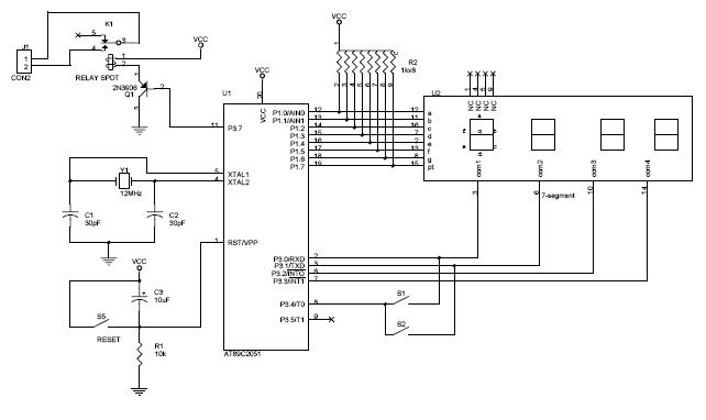
Overall, this digital clock project exemplifies the integration of microcontroller technology with basic electronic components to create an effective timekeeping device. The design principles and circuit layout can serve as a foundation for further developments or enhancements in digital clock applications.Digital clock project based on the PIC16C54 microcontroller can be designed using the following circuit diagram. This digital clock electronic project based on the PIC16C54 is a simple time-of-day clock incorporating four seven-segment LED displays and three input switches.
There is also an additional reset switch that would not normally be incor porated into the final design. The common cathode for each display is turned on with transistors connected to the four I/O lines of PORTA. A low output turns on the PNP transistor for the selected display. The PORTB pins activate the LED segments. Pressing SW1 will cause seconds to be displayed. The time is set by pressing SW2 to advance minutes, and SW3 to advance hours. The displays used were common cathode and turned on with transistors to avoid trying to sink too much current into the PIC16C5X.
100 W resistors were used in series with the segments to obtain the desired brightness. Different values may be required if different displays are used. This digital clock project based on the PIC16C54 microcontroller ( circuit and software ) was designed by Dan Matthews Microchip Technology Inc. Download Source Code 🔗 External reference
Related Circuits
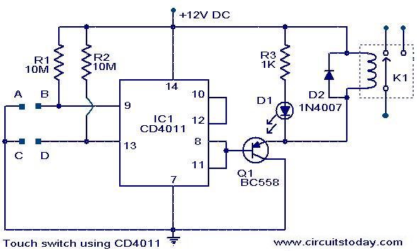
A simple touch switch circuit using the CD4011 is presented. The CD4011 integrated circuit (IC) is configured as a flip-flop. Pins 9 and 13 of the IC function as the set and reset terminals, respectively. CMOS ICs like the...
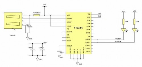
Some still remember the serial RS232 port, also referred to as a COM PORT, as its functionality has largely been replaced by USB ports. However, for electronics engineering students and technicians learning about computer interfaces, the RS232 port remains...
This is a circuit monitoring device. It runs for over 10 days and can log up to 32k events both digital and analog. Samples are logged either on a timing basis (0.01 to 2.5 seconds), or on a triggered...

This is a simple water level alarm circuit made using a 555 timer IC. The circuit will produce an alarm when the water level reaches a preset level. The water level alarm circuit utilizing a 555 timer IC is designed...
The circuit diagram above illustrates the Clock Controller V1.1. Pins P3.0 to P3.3 are connected to the base of a 4-PNP transistor, specifically the 2N2907, which is used to sink current. The Clock Controller V1.1 circuit is designed to manage...
This weblog focuses on electronic circuit schematics, PCB design, DIY kits, and diagrams for electronic projects. A simple circuit utilizing the NE555 IC is presented, which can be employed to generate metronomes. This circuit is particularly beneficial for music...