
Touch switch using CD4011

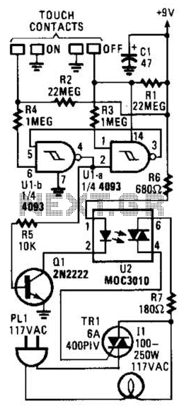
The touch switch circuit utilizing the CD4011 is a practical example of a capacitive touch interface. The CD4011 is a quad 2-input NAND gate CMOS IC that can be configured to operate as a bistable multivibrator or flip-flop, allowing for the toggling of output states based on input conditions. In this circuit, the resistors R1 and R2 serve to pull the set and reset pins to a high logic level, ensuring that the flip-flop remains in a stable state until a touch event occurs.
When a user touches points A and B, the capacitance introduced by the human body influences the voltage levels at the gates connected to pins 9 and 13. This momentarily pulls the gates low, which changes the output state of the flip-flop. The output low state triggers transistor Q1, which may be an NPN transistor, allowing current to flow through the relay coil, thereby closing the relay contacts and powering the connected load.
The relay used in this circuit should be selected based on the voltage and current requirements of the load it controls. It is essential to ensure that the transistor Q1 can handle the relay's coil current without exceeding its maximum ratings. Additionally, a flyback diode should be connected in parallel with the relay coil to protect the transistor from voltage spikes generated when the relay is deactivated.
Upon touching points C and D, the gates are again driven high, which resets the flip-flop and turns off the transistor Q1, thereby opening the relay contacts and cutting power to the load. This design allows for a simple yet effective method of controlling electrical appliances through touch, enhancing user interaction while maintaining low power consumption thanks to the characteristics of CMOS technology.A simple touch switch circuit using CD4011 is given here. The IC CD4011 is wires as a flip flop here. The 9, 13 pins of the IC works as the set and reset contacts respectively. CMOS ICs like 4011 require requires a very low current for controlling its gates. Since the pins 9 and 13 are connected to the positive via resistors R1 and R2, the logic ga tes of the ICs will be in high state. When we touch through the points A, B the gates of the IC will be closed and the output becomes low. This switches ON the transistor Q1 and the relay gets activated. When we touch through the points C, D the gates again becomes high and switches the transistor OFF. This makes the relay OFF. Thus by touching through the contact points A, B and C, D the appliance connected through the relay can be switched On and OFF. 🔗 External reference
Related Circuits
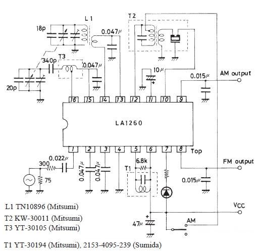
A very simple FM IF MW radio receiver circuit can be designed using the LA1260 IC manufactured by Sanyo Semiconductor. This FM IF MW radio receiver circuit schematic shows that the LA1260 IC can be utilized in AM and...
Integrated AF power amplifiers have experienced significant advancements in recent years, offering enhanced power and ease of use. The TDA1519C from Philips features two power amplifiers that provide 11 W per channel in stereo mode or 22 W in...

The circuit utilizes a 555 timer IC to create a lighting group delay effect, as illustrated in Figure 2-46. It consists of the 555 IC along with a resistor and capacitor configuration that establishes the delay. The circuit remains...
Utilize this cell phone charger circuit along with a 1.5V battery when there is no main power available and charging your phone is necessary. This cell phone charger circuit is designed to provide a reliable charging solution using a 1.5V...
In this circuit, two 567 tone decoders are utilized. One functions as an oscillator, while the other acts as a detector. Connecting TP1 and TP2 allows U2 to receive the signal from U1, resulting in pin 8 of U2...

This circuit is a touch switch circuit, similar to a touch door alarm. It utilizes a 555 timer as the core component of the touch switch circuit. The operation begins when the plate is touched, triggering the 555 timer....