
Full Duplex Digital Fiber Optic Voice Link

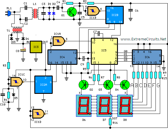
The project involves a detailed design of both the LED driver and photo-detector circuits, crucial for establishing a reliable fiber optic communication link. The LED driver circuit utilizes the 2N7000 MOSFET, which operates effectively as a switch, allowing for rapid modulation of the LED. This rapid switching capability is essential for transmitting digital signals across the fiber optic medium. The LED emits light when the MOSFET is activated, transmitting information encoded in the light signal.
On the receiving end, the photodiode is strategically reverse-biased to enhance its response time and linearity, which is vital for accurately detecting the incoming light signals. The trans-impedance amplifier is designed to convert the photocurrent generated by the photodiode into a voltage signal, which is then processed by an inverting amplifier to match the required output voltage levels. This amplification stage ensures that the signal remains within the desired range for subsequent digital processing.
The inclusion of a second-order Sallen-Key low-pass filter is a critical design choice, as it allows for effective attenuation of unwanted high-frequency noise while preserving the integrity of the audio signal. The filter's cut-off frequency is optimized for human speech, ensuring clear communication.
The synchronization of the data transmission is achieved through the use of clock signals generated by the SN54HC393 binary counter, ensuring that the audio data is correctly timed for both sending and receiving ends. This synchronization is essential for maintaining data integrity over the fiber optic link.
Overall, the design prioritizes performance, reliability, and clarity in audio transmission, making it suitable for applications requiring high-quality voice communication over fiber optic networks.The goal of this project is to design and build a full duplex digital fiber optic voice link over a length of 50m at minimum data rate of 64 kbps. The cores of this project are the designs of LED driver and photo-detector circuits. From the preceding circuit diagram, it only shows one side of the circuit. The other side of the circuit is just a du plicate from this circuit. The only part that you need to notice is the output of the LED driver is connected to the photo-detector circuit on the other side, and vice versa. The condenser microphone is biased with a 9V supply and a 4. 7k ohm load resistor. Recall that electret condenser microphone need biasing because of the built-in FET amplifier inside the microphone capsule.
The AC-coupling capacitor is used as a high pass filter to block the DC offset, so the microphone signal is AC coupling. Since this audio amplifier is built specifically for audio signal, so this amplifier can not be used as any other general-purpose op-amps.
This circuit here is used from the datasheet, which gives a gain of 50. In case of signal distortion, a 10K potentiometer is used to control the amplitude of the input signal. Again, the 220uF AC-coupling capacitor is used to block the DC offset. This second-order sallen-key low pass filter is designed to have a 3. 5kHz cut-off frequency, which bandwidth is sufficient for human speech. We used this specific filter over the typical RC filter because we obtain a sharper roll off and much less noise.
The 256kHz clock signal is generated by a signal generator, and it is mainly used as a master clock and bit clock for the audio encoder. The 8kHz clock signal obtained by using the SN54HC393 dual 4-bit binary counter, which divided the 256kHz signal by 32.
This 8kHz clock signal is used to synchronize the transmit data bytes and receive data bytes. This integrated circuit has an internal encoder and decoder that convert the analog signal to digital form, and digital to analog form respectively. This circuit is used from the datasheet, which is built for signal ended analog input and output. Again, this circuit is used from the datasheet. This is a typical LED driver using a N-channel MOSFET as a digital switch. The advantage of using MOSFET prior to BJT or Op-amp due to is the excellent slew rate. After testing with many different MOSFET, the 2N7000 has the best slew rate. Here, the LED is forward biased, and light on when the source side (input) of the MOSFET is HIGH. A high-speed photodiode detector is used to transduce the photon to electrical current. In this case, the photodiode is reverse-biased because the load line is much more linear. Next, the trans-impedance amplifier will convert the current into voltage, which will amplify again with an inverting amplifier so the amplitude is 0 to 5V.
When we were choosing the op-amp for this circuit, we had the same principle, which is the highest slew rate as possible. Since the gain of the op-amp is inverse proportion to the the slew rate, the gain must adjusted so it won`t affect the signal by the low slew rate.
🔗 External reference
Related Circuits
This circuit is designed for precise measurement of temperature in degrees Celsius. It includes a transmitter section that converts the output voltage from the sensor, which is proportional to the temperature being measured, into a frequency signal. This frequency...
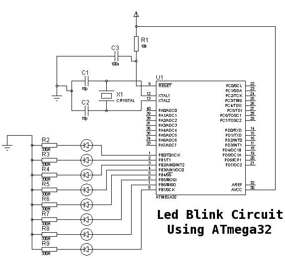
This is a basic tutorial for beginners using the ATmega32 microcontroller to get started. This program can be referred to as a "Hello World" for the ATmega. The ATmega32 microcontroller is a member of the AVR family, widely utilized in...
This application note describes the creation of a heart rate monitor utilizing an infrared (IR) LED and a phototransistor pair, with the waveform observed at the output of the phototransistor. The purpose of this project is to demonstrate a...
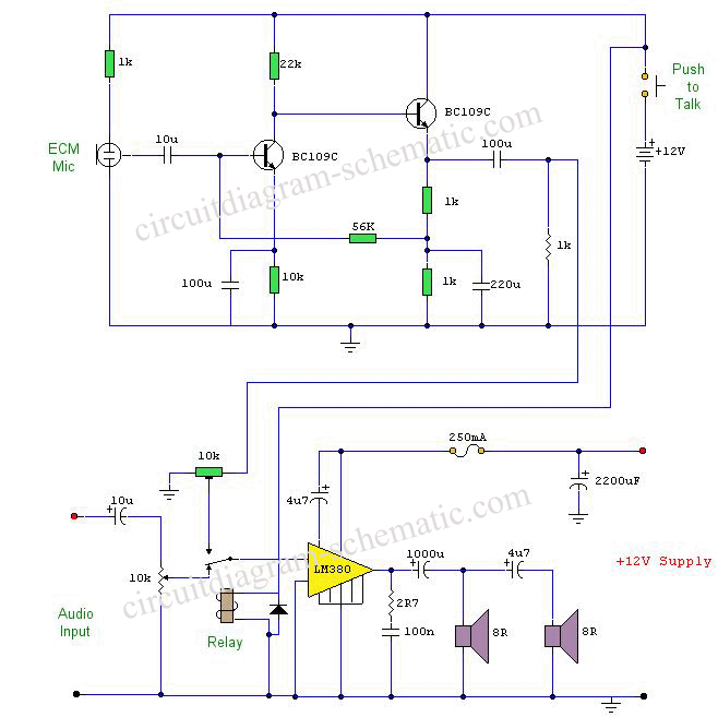
This circuit diagram represents a microphone preamplifier, specifically designed to prioritize voice signals over other audio inputs. In its basic configuration, the circuit includes a microphone unit and a change-over switch that connects to an amplifier. When the push-to-talk...
The SP6691 circuit is designed to provide a high output voltage using a lower voltage boost regulator by incorporating a charge pump circuit. This configuration can convert a standard 30V boost regulator into a 60V boost regulator if necessary....
A signal conditioner for a pH meter probe requires high input impedance. The signal conditioning of the pH meter probe is achieved by incorporating a buffer. The design of a signal conditioner for a pH meter probe is critical for...