
UM3561 electronic siren circuit diagram

The UM3561 integrated circuit is central to the operation of this siren alarm circuit. It is designed to generate audio signals that replicate various emergency sounds, making it suitable for alarm systems or alert applications. The circuit is straightforward, requiring only a few passive components to function alongside the IC, which simplifies the design and reduces the overall footprint of the circuit.
The power supply requirement of around 3 volts is typical for low-power applications, allowing for the use of small batteries or low-voltage power sources. The low current consumption of the UM3561 enhances the efficiency of the circuit, making it ideal for battery-operated devices where prolonged operation is essential.
The ability to generate four different sound types is a significant feature of the UM3561. Each sound can be selected using external control mechanisms, such as switches or microcontroller outputs, allowing for versatility in applications. The police siren sound is characterized by its alternating pitch, which is effective for alerting individuals in various environments. The fire engine siren sound provides a continuous tone that is easily recognizable, while the ambulance siren combines both tones to signal urgency. The machine gun sound adds a unique audio effect, which can be used in specific scenarios, such as theatrical productions or special effects.
Overall, the UM3561-based siren alarm circuit is a compact and efficient solution for generating emergency alert sounds, making it suitable for various applications, including security systems, toy designs, or educational projects in electronics.This siren alarm circuit diagram is based on a specialized IC UM3561, which is a low power CMOS LSI specially designed for this type of applications. The UM3561 contains all needed parts ( oscillator, selector circuits, programmed mask ROM ) to simulate siren sound using few external components.
The siren circuit require a power supply circui t around 3 volts and has a low current. The UM3561 siren sound generator circuit has possibility to generate four types of sounds : police siren, fire engine siren, ambulance siren and machine gun sound. 🔗 External reference
Related Circuits
These two tank circuits appear to broaden the operating spectrum. The accompanying information sheet indicates that when both circuit stages oscillate at the same frequency, the power output reaches its maximum. This suggests that if the tunable tank circuit...

The circuit operates as an astable multivibrator, generating a square wave signal at a specific frequency. When powered, the circuit will function continuously. The astable multivibrator circuit is a type of oscillator that produces a continuous square wave output without...
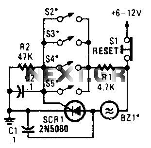
Four parallel switches are employed to monitor four positions. When any switch is closed, SCR1 is triggered, activating the alarm. The alarm is designed to be of the non-interrupting type. The circuit consists of four parallel switches, each representing a...
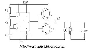
The timer IC (NE555) is configured as an astable multivibrator in this circuit. It generates an alternating non-sinusoidal output waveform as soon as a supply voltage of 12V is applied. Therefore, alternating voltage is produced from direct current (battery)....
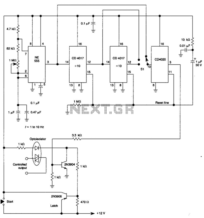
By using three 555 ICs, three sequential pulses can be generated. Output 3 can be connected back to the trigger input to achieve astable operation. The circuit described utilizes three 555 timer integrated circuits (ICs) configured to generate three sequential...
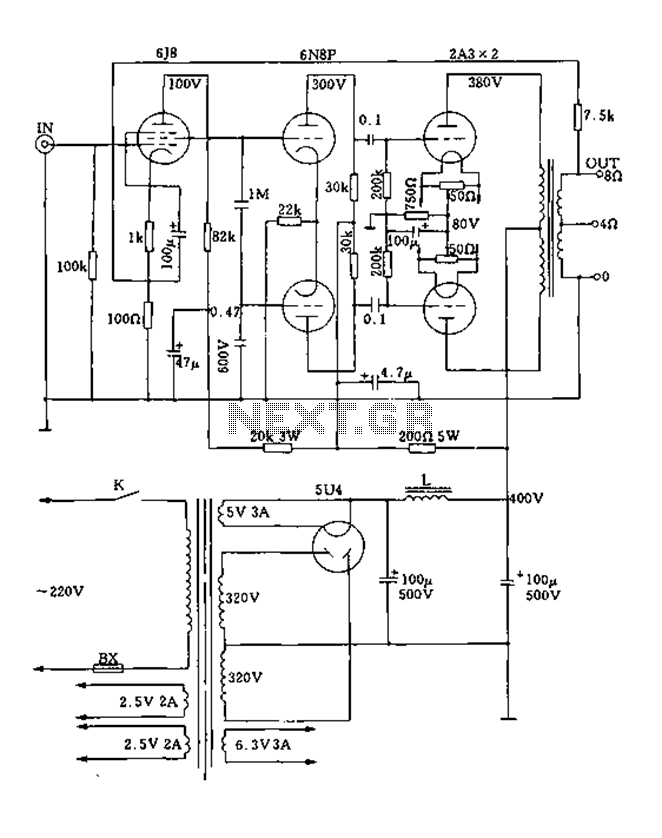
FIG. 2A3A is a low direct thermal resistance transistor with a resistance of only 800 ohms. The output transformer has a primary screen to load impedance of 3.5k ohms. The push-pull amplifier tube operates with a screen voltage ranging...