
Digital Remote Thermometer

The circuit employs a remote temperature sensor that communicates its readings over the mains electricity supply. This method of data transmission utilizes power line communication (PLC), which allows for the simultaneous transmission of sensor data and AC power. The temperature sensor is likely to be a thermistor or a digital temperature sensor, capable of providing accurate readings within the specified range of 00.0 to 99.9 °C.
The design of the circuit includes a power supply section that ensures proper voltage levels for both the sensor and the communication interface. The sensor's output is conditioned to be compatible with the PLC system, which may involve signal modulation techniques to encode the temperature data effectively onto the AC waveform.
To enhance precision, the circuit may incorporate an analog-to-digital converter (ADC) that digitizes the sensor output, allowing for more accurate readings and easier integration with digital communication protocols. Filtering components would be included to minimize noise and interference from the mains supply, ensuring that the transmitted data remains reliable.
The circuit should also feature protective elements such as fuses or circuit breakers to safeguard against overcurrent situations, as well as isolation components to prevent high-voltage spikes from affecting the sensor circuitry. Overall, this remote sensor circuit is designed to provide accurate temperature monitoring while leveraging existing infrastructure for data transmission.Remote sensor sends data via mains supply, Temperature range: 00.0 to 99.9 °C This circuit is intended for precision centigrade temperature measurement, w.. 🔗 External reference
Related Circuits
This document serves as a resource for developers who are new to Texas Instruments (TI) ARM-based processors, as well as for seasoned developers seeking to deepen their understanding of the different ARM architectures. It starts with an overview of...
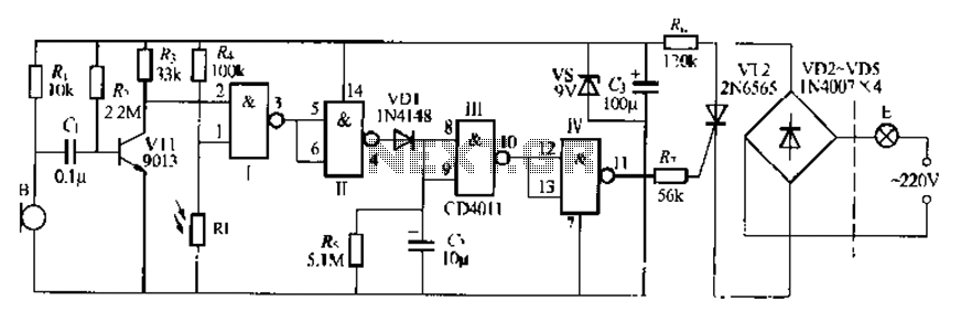
The CDI011 integrated circuit is designed for a sound and light-controlled stair delay switch circuit, which is relatively simple and effective. It utilizes a combination of NAND gates and differential input dynamics. The circuit has two input terminals; when...
This circuit provides a visual 9-second delay using a 7-segment digital readout LED. When the switch is closed, the CD4010 up/down counter is preset to 9, and the 555 timer is disabled, holding the output high. When the switch...
This design is for a thermometer circuit that utilizes the LM35 integrated circuit (IC) as a temperature sensor. It is a straightforward circuit that allows for the measurement of room temperature using a digital voltmeter or any voltmeter capable...
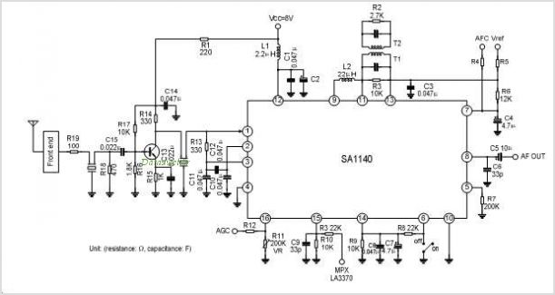
The SA1691 is a monolithic integrated circuit designed for radio cassette tape recorders, clock radios, and headphone radios. This IC includes all functions from the antenna to the audio power amplifier of AM/FM radio, produced by Silan. The SA1691 integrated...
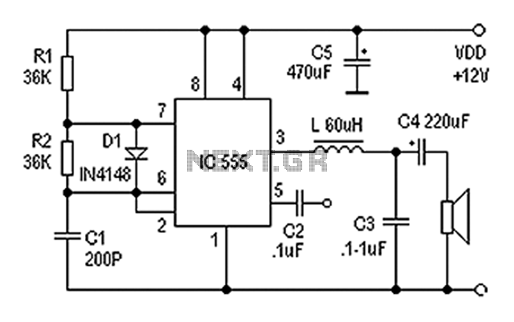
Also known as a digital amplifier, the Class-D amplifier is characterized by its compact size and high efficiency. This circuit utilizes a 555 timer IC to create a Class D amplifier. The 555 timer operates as a controllable multivibrator,...