
fahrenheit thermometer circuit

This thermometer circuit leverages the LM35 temperature sensor, which provides an output voltage proportional to the temperature in degrees Celsius. The LM35 operates over a wide temperature range, typically from -55°C to 150°C, with a linear output of 10 mV/°C. This means that at 25°C, the output voltage will be 250 mV.
To accurately measure the voltage output from the LM35, it is essential to utilize a voltmeter with high input impedance to avoid loading effects that could distort the readings. The floating output voltage indicates that the circuit does not have a direct ground reference, which is a design consideration when connecting to measurement devices. If the voltmeter is single-ended and references ground, a separate power supply is required to avoid ground loops and ensure accurate readings.
The differential input adapter serves to convert the floating output of the LM35 into a form that can be interpreted by a single-ended voltmeter. This adapter typically includes operational amplifiers configured in a differential mode, allowing the circuit to measure the voltage difference between the output of the LM35 and a reference voltage.
The circuit can be designed with additional features, such as an adjustable gain to allow for different measurement ranges or a calibration mechanism to ensure accuracy. In practice, setting the voltmeter to the 200 mV range allows for a straightforward conversion of the measured voltage to temperature in degrees Fahrenheit, simplifying the user experience and enhancing the utility of the thermometer circuit.
Overall, this thermometer circuit design is suitable for various applications, including environmental monitoring, HVAC systems, and educational purposes, providing a reliable and easy-to-implement solution for temperature measurement.This is a design for thermometer. This is a simple circuit design. This circuit is based on temperature sensor using LM35 Ic. If you have a digital voltmeter, or any voltmeter with millivolt resolution and high input impedance, then you can use this temperature-to-voltage adapter circuit to measure room temperature. This is the figure of the circu it. Note that the voltage output of this circuit is floating, not referenced to ground. You have to use separate supply if your voltmeter has single ended (referenced to ground) input. Differential input adapter described here is suitable to give a differential input for your single ended meter, remember that the input impedance must be high. You can set your voltmeter to 200 mV range to give temperature reading directly in Fahrenheit degree.
🔗 External reference
Related Circuits
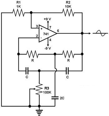
This circuit generates a sine wave using a single operational amplifier (741). The feedback loop of the op-amp includes a twin-T filter connected between its output and inverting input. Positive feedback for oscillation is provided by resistor R2. The...
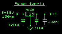
This circuit is a small +5V power supply, which is useful when experimenting with digital electronics. Small inexpensive wall transformers with variable output voltage are available from any electronics shop and supermarket. Those transformers are easily available, but usually...

This document outlines a straightforward process to transmit voice over a distance using amplitude modulation of light through sound vibrations. It details how modulated light is detected and demodulated by a receiver to reproduce sound. The experiments described are...
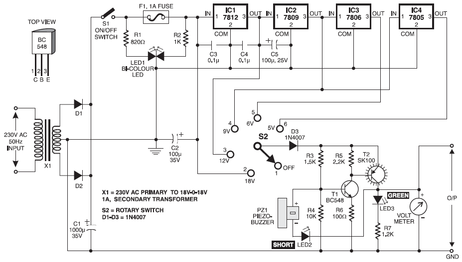
Stabilized DC Power Supply with Short-Circuit Indication. The circuit provides four distinct regulated DC outputs (12V, 9V, 6V, and 5V) along with an unregulated 18V DC output, selectable via a rotary switch S2. The chosen output is displayed on...
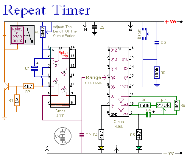
The CMOS 4060 integrated circuit (IC) features two built-in inverters located at pins 9, 10, and 11, which must be interconnected to create an oscillator. The output of this oscillator is available at Pin 9, which continuously alternates between...
The LAN tester circuit can also test cables such as telephone, coaxial, LAN, and others. This circuit uses LEDs as the main indicator device. The LAN tester circuit is designed to verify the integrity and functionality of various types of...