
digital switching system

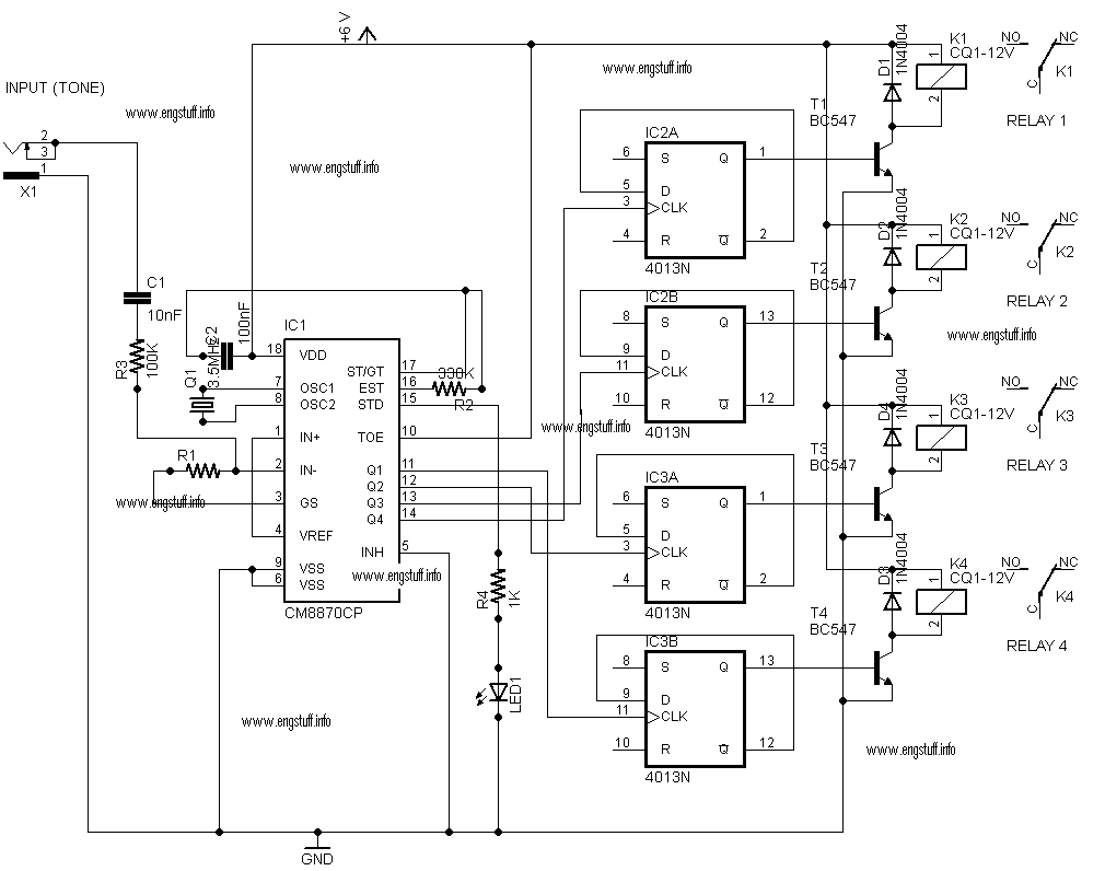
The circuit design incorporates a systematic approach to control multiple devices efficiently using a minimal number of components. The up/down counter (IC1) serves as the core of the system, facilitating both increment and decrement operations through user interaction with the push-to-on switches. The use of a presettable counter allows for flexibility in starting the count from any desired value, enhancing usability.
IC2, as a 1-of-16 decoder, translates the BCD output from the counter into a binary format that identifies which specific channel is currently selected. This is crucial for systems where multiple devices must be controlled independently. IC3 complements this function by ensuring that the selected channel is activated; it outputs control signals that correspond to the channel indicated by IC2.
The inverter gates (IC4 through IC6) play a vital role in ensuring that the triacs receive the correct polarity of signals for operation. This conversion from negative-going to positive-going pulses is necessary because triacs require a specific triggering method to operate effectively. The inclusion of NPN transistors allows for the amplification of control signals, providing sufficient current to drive the triacs, which are responsible for switching the connected devices on and off.
Furthermore, the diodes connected in series with the triac gates serve a protective function, ensuring that the gate receives a unidirectional current, thereby preventing potential damage to the triac from reverse polarity. This design consideration enhances the reliability and longevity of the circuit, making it suitable for various applications where multiple device control is necessary. Overall, this circuit exemplifies an efficient design for controlling multiple outputs with minimal user input while providing clear visual feedback.This circuit can control any one out of 16 devices with the help of two push-to-on switches. An up/down counter acts as a master-controller for the system. A visual indication in the form of LEDs is also available. IC1 (74LS193) is a presettable up/ down counter. IC2 and IC3 (74LS154) (1of 16 decoder/demultiplexer) perform different functions, i. e . IC2 is used to indicate the channel number while IC3 switches on the selected channel. Before using the circuit, press switch S1 to reset the circuit. Now the circuit is ready to receive the input clock. By pressing pressing switch S2 once, the counter advances by one count. Thus, each pressing of switch S2 enables the counter to advance by one count. Likewise, by pressing switch S3 the counter counts downwards. The counter provides BCD output. This BCD output is used as address input for IC2 and IC3 to switch one (desired channel) out of sixteen channels by turning on the appropriate triac and the corresponding LED to indicate the selected channel. The outputs of IC3 are passed through inverter gates (IC4 through IC6) because IC3 provides negative going pulses while for driving the triacs we need positive-going pulses.
The high output of inverter gates turn on the npn transistors to drive the triacs. Diodes connected in series with triac gates serve to provide unidirectional current for the gate-drive. 🔗 External reference
Related Circuits
This Project Digital Calendar using Microcontroller is an advanced digital calendar, which displays the Date, Day, Month over the LED display. It has an 8 bit Microcontroller which runs on the Program embedded on its ROM. Separate LEDs are...
The objective of this digital electronics project is to record messages using a dedicated voice recorder integrated circuit. Recordings are stored in non-volatile memory cells, ensuring that messages remain saved even when power is removed from the device. The...
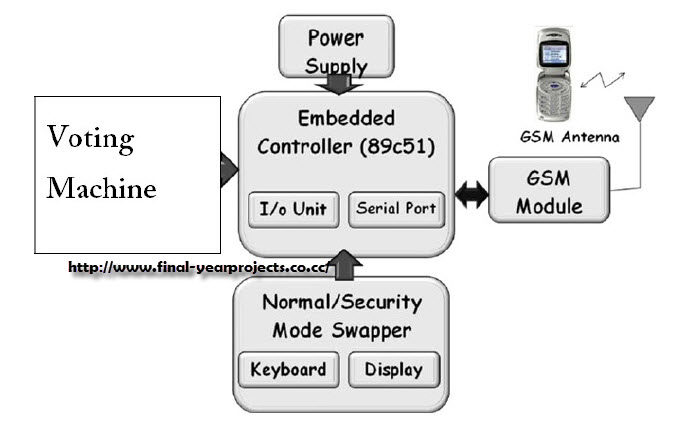
This project involves a GSM-based voting machine system that utilizes AT commands to send SMS through a microcontroller. It operates in two modes: Normal mode, where an authorized individual from a local area can cast their vote, and Security...
Figure 7-2 illustrates the FSK (Frequency Shift Keying) signal demodulation circuit, which is built using a digital phase-locked loop. This circuit features two oscillators operating at distinct frequencies: crystal oscillator X with a frequency of 983.04 kHz and crystal...
This is a personal website showcasing various projects developed during spare time, many of which are related to electronics and Linux. The website itself is one of these projects. It also features a section with pictures from places visited...
This is a digital clock schematic diagram. The circuit is relatively complex and may pose challenges for beginners due to the intricate connections involving integrated circuits (ICs). The circuit operates with two voltage supply lines. The voltage +5VA powers...