
DIGITAL THERMOMETER CIRCUIT

The circuit's design integrates various components to achieve accurate temperature measurement and display. The LM334 temperature sensor operates as an adjustable current source, allowing for flexibility in the measurement range. The output current from the LM334 is converted into a voltage signal, which is then processed by the LF353 dual op-amp configured as a summing amplifier. This setup enables calibration for different temperature units by adjusting the 10K potentiometer, ensuring that the displayed temperature aligns with the desired scale.
The voltage-to-frequency converter, specifically the 9400, takes the calibrated voltage output from the inverting amplifier and converts it into a frequency signal. This frequency is crucial for driving the BCD counter, which counts the pulses generated by the V/F converter. The NE555 timer provides a stable timing reference, ensuring accurate pulse generation for the counter.
The 74LS00 NAND gate plays a pivotal role in processing the gating signal that synchronizes the clock signal for the BCD counter. This allows for precise counting and display of the temperature data. The MC14553 BCD counter translates the frequency input into a binary coded decimal format, which is then sent to the MC14543 decoder/driver/latch. This IC converts the BCD output into a format suitable for driving the three seven-segment displays.
The three PNP switching transistors control the power to the seven-segment displays, allowing for efficient operation and reduced power consumption. The overall design results in a reliable and user-friendly temperature measurement system, capable of displaying temperatures in multiple units with high accuracy.This circuit is composed of a temperature sensor, amplifier, V/F converter, three digit binary coded decimal (BCD) counter, time base and seven segment led displays. In addition to the 9400 V/F converter, other ICs need for this project include the LM334 temperature sensor, LF353 dual op amp, NE555 timers, 74LS00 NAND gate, MC 14553 three digit
BCD counter, MC 14543 BCD to 7 segment decoder/driver/latch, and three seven segment LED displays with three PNP switching Transistors. The output of temperature sensor changes linearly as a function of temperature. The output is connected to a summing amplifier, which is used to calibrate the output of the temperature sensor for a desired temperature type (K, C or F) and an intended range.
That is, to display the temperature in K, C or F, you have to adjust the 10K POT according to suit the voltage appears at the output of the summing amplifier. Since the output of the temperature sensor is directly proportional to the temperature changes. The output of the Inverting amplifier is the input of Voltage to Frequency converter, therefore the output frequency of the converter is directly proportional to the output voltage of the inverting amplifier.
The output frequency of the converter is then ANDed with the gating signal to produce the clock signal for the tree digit BCD counter. The BCD output of the counter drives the three bit LED display sequentially via the BCD to 7 segment decoder and the temperature is displayed on the LED.
The temperature sensor LM334 is a three terminal adjustable current source whose current can be programmed from 1 A to 10mA with one external Resistor. The three terminals are labelled +V, R and -V. The pin out is shown above. 🔗 External reference
Related Circuits
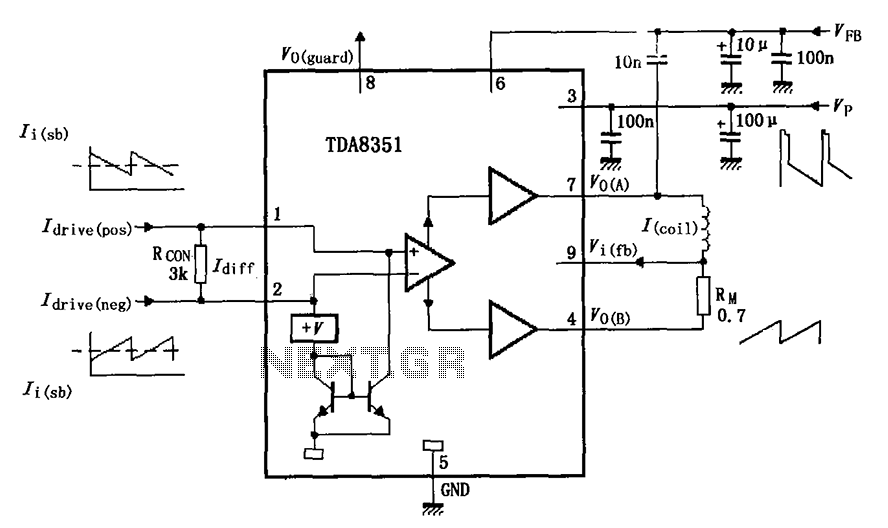
The figure illustrates the actual application circuit for the TDA8351/8356. In this circuit, a 50V voltage feedback (VFB) is connected in series with a 33-ohm resistor. Signals are input at pins 1 and 2, where pin 1 receives a...
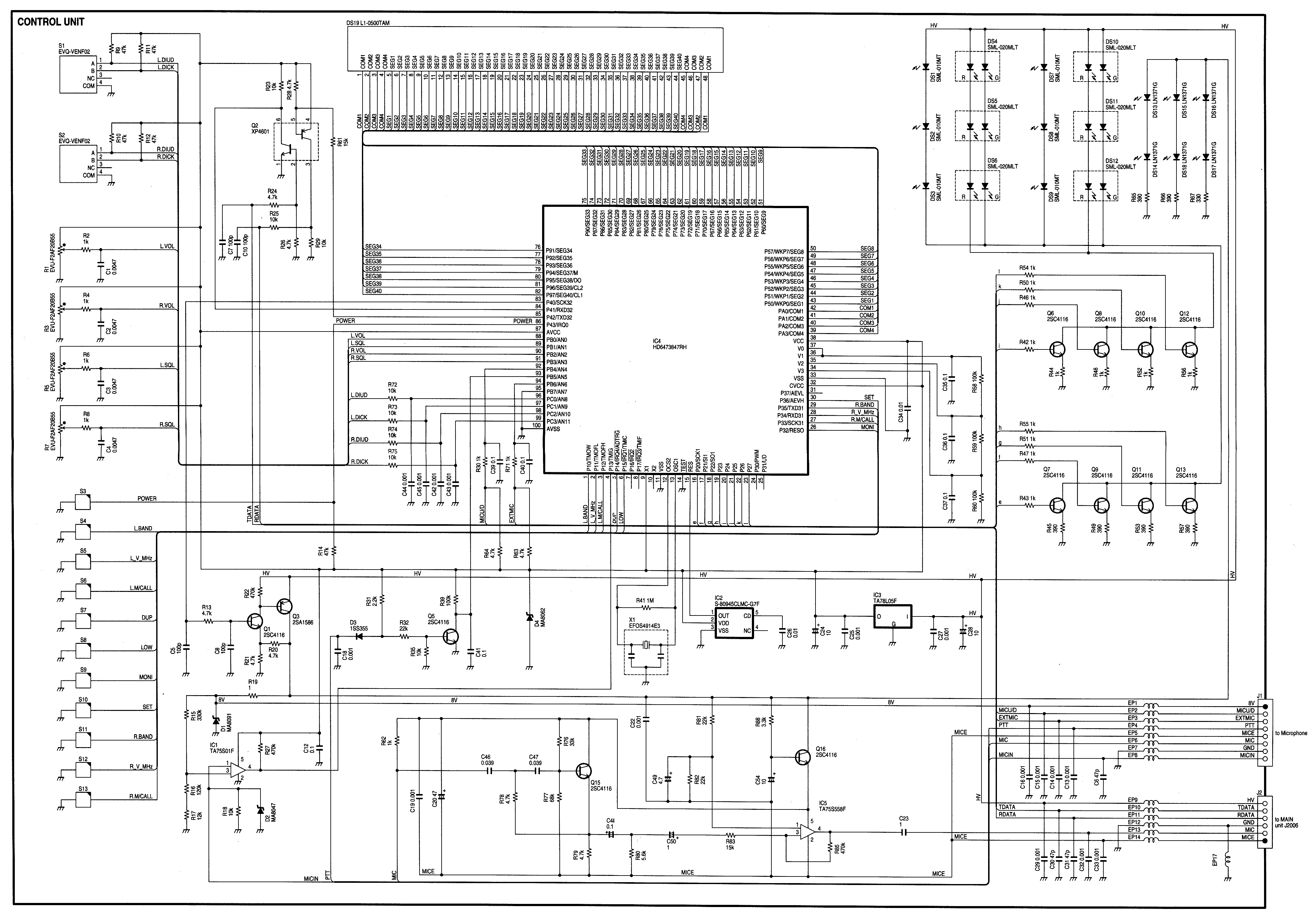
Radio Control Circuits PDF Manual Download. This document serves as a comprehensive guide to radio control circuits, intended for individuals seeking to understand the principles and applications of radio frequency (RF) technology in controlling various devices. The manual covers fundamental...

To ensure proper operation of the transistor in a circuit, it is essential to measure the reverse breakdown voltage of the transistor. This is particularly important for tubes with high reverse breakdown voltage requirements, such as those used in...
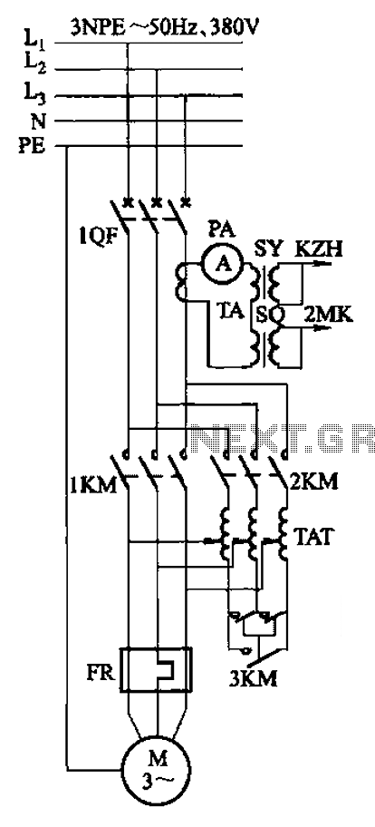
Autotransformer voltage starting, with an adjustable starting time of 30-60 seconds. It includes the SDJ electrode liquid level sensor of HJ-13 type, a pump control system box of HKD-21B type, 1MK level modules adopted by HKG-1SG type, 2MK start...
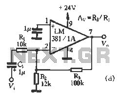
National Semiconductor (NS Company) produces audio integrated circuits (ICs) that offer wide frequency response and low noise. These circuits provide excellent performance across all NS products. The circuit illustrated in Figure 3-12 includes a preamplifier and a singing equalizer...
This single transistor audio mixer is utilized in an amplifier circuit design featuring a base-driven transistor, with its emitter being current-controlled. This audio mixer circuit employs a single transistor to facilitate the mixing of audio signals. The transistor operates in...