
Diode Digital Thermometer Circuit

The digital thermometer circuit leverages the characteristics of the 1N4148 diode, which has a well-defined temperature coefficient. As the temperature changes, the forward voltage drop across the diode varies, allowing it to serve as an effective temperature sensor. The temperature coefficient of -2 mV/°C indicates that for every degree Celsius increase in temperature, the forward voltage drop decreases by approximately 2 millivolts.
In the circuit, the 1N4148 diode is connected in a forward-biased configuration. The voltage across the diode is measured using an analog-to-digital converter (ADC), which converts the analog voltage signal into a digital representation for further processing. A microcontroller can be utilized to interpret the digital signal from the ADC and convert it into a temperature reading.
To enhance accuracy, the circuit may include calibration features, such as a potentiometer, which allows for fine-tuning of the output to match known temperature references. Additionally, it is advisable to implement filtering techniques in the circuit design to minimize noise and improve measurement stability.
Power supply considerations are also crucial. The circuit should be powered by a stable voltage source to ensure consistent performance. A bypass capacitor may be added near the power supply pins of the microcontroller to filter out any high-frequency noise that could affect the ADC readings.
Overall, this digital thermometer circuit is a cost-effective solution for temperature measurement, utilizing the 1N4148 diode's properties to provide accurate readings in a compact design.This digital thermometer circuit diagram uses a common 1N4148 diode as the temperature sensor. The temperature coefficient of the diode, -2 mV/°C is ex.. 🔗 External reference
Related Circuits
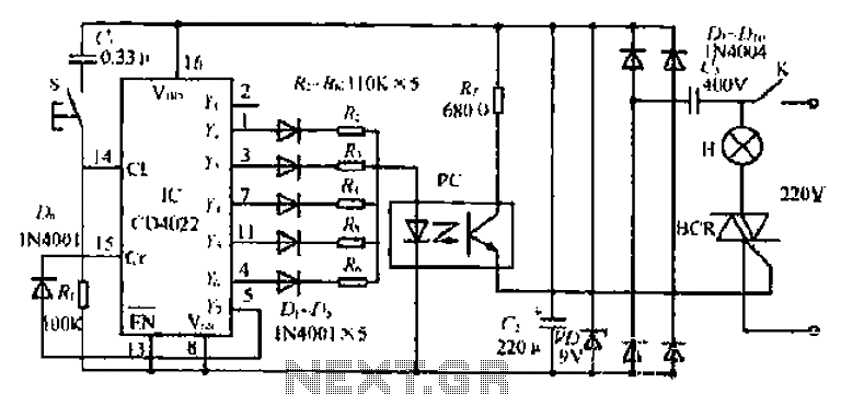
The 1C foot VIII developed a training device, utilizing the trigger terminal CI for a positive input pulse. It concludes by providing a quotient output level. The system involves a commercial electric circuit featuring a buck converter, which limits...
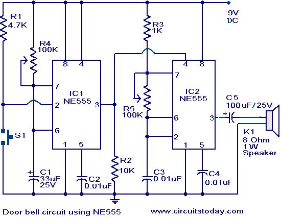
The primary components of this doorbell circuit are two NE555 timer integrated circuits (ICs). When switch S1 is pressed momentarily, the loudspeaker emits a bell tone for the duration determined by the monostable multivibrator configuration around IC1. Pressing switch...
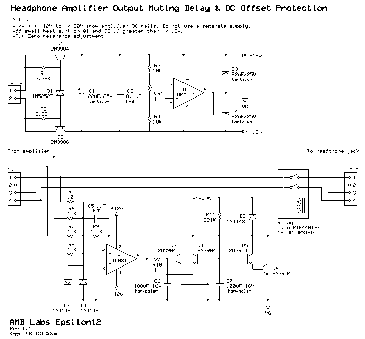
A low-pass filter is a stable state-space system that has an input and produces an output. If the input is a quasi-periodic signal, the output will be the same quasi-periodic signal with a phase shift. The key difference is...
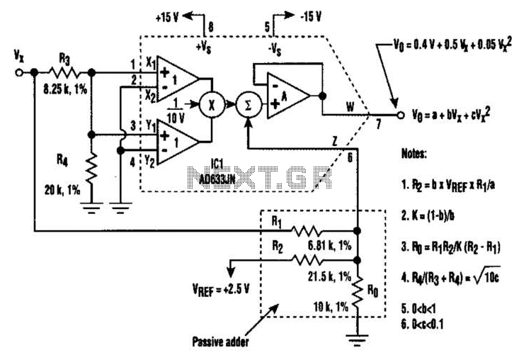
A circuit utilizing a single analog multiplier and five precision resistors can produce an output voltage (Ko) that represents a second-order polynomial. This circuit implements the quadratic function. The input terminals of IC1 are configured to create a positive...

The PM4040F is utilized in switching power supply applications for medium power ranges. It is designed to drive power supplies between 200W and 800W, as illustrated in the accompanying bridge circuit. For power applications below 1000W, an alternative circuit...
The electronic components designed by conventional electronic bonsai create a sparkling and brilliant atmosphere in the living room, enhancing the joys and pleasures of life. The selection of components includes IC1 to IC4, which consist of two pairs of...