
Digital Up / Down Counter

The circuit utilizes the CD40110BE, a versatile up/down counter integrated circuit (IC), designed for counting applications. This IC can source up to 25 mA per segment, making it suitable for driving common cathode seven-segment displays, which are essential for visualizing the count. The design mandates the use of common cathode displays for proper functionality, ensuring that all segments illuminate brightly and uniformly.
Resistor values are crucial for limiting the current flowing through the display segments. For a supply voltage of up to 12 volts, a minimum resistor value of 680 Ohms is recommended. If the supply voltage exceeds 12 volts, up to a maximum of 18 volts, or if reduced current is desired, resistor values can be increased to 1500 Ohms. This adjustment allows for greater control over power consumption and display brightness. The approximate current flowing through each segment can be calculated using the formula: (Supply Voltage - 2V) / Resistor Value, where 2V accounts for the forward voltage drop across the LED segments.
The schematic provided illustrates the connections for the first, second, third, and last stages of the counter. The design supports counting up to 9999 by utilizing four CD40110BE ICs, with the flexibility to expand the circuit by adding more stages if needed. Each stage functions similarly, allowing for modular expansion based on the desired number of digits to be displayed.
In addition to the basic counting functionality, the circuit can be modified to include various options. For instance, integrating a clock circuit with a frequency of 1 Hz in place of the reset switch transforms the setup into a frequency counter, measuring counts in Hz/second. Alternatively, a 1 Hz clock signal can be fed into one of the inputs to create a timer that counts up or down. While not highly accurate, a simple 555 timer circuit can also serve as a basic clock source for this application, providing additional flexibility in timing and counting operations.This Circuit uses a CD40110BE, Up/Down Counter IC's. This IC is able to Source Each Segment with 25 mA, Giving a Very Nice Bright Display. The 7 Segment Displays MUST be a Common Cathode Type, as I have used here. All the UnMarked Resistors should be at least 680 Ohms for Up To 12 Volts Supply Voltage. For Higher Supply Voltages up to 18 volts or Reduced Currents, I would suggest Increasing these Values to 1500 Ohms. Or if you want "Reduced Power" and "Brightness", Adjust the resistor values as appropriate. Basically the Approximate Current is Supply voltage Minus 2, Divided by the Resistor Value. The Schematic posted here Only shows the First, Second, Third and Last Stages. And This board is for a counter of up to 9999. However: Since All Stages between the Third and Last, Would be the same, So you could make a display with as many digits as you wish, by expanding the circuit board. Additionally: You can just put in 1, 2, 3, or all 4 IC's and the Appropriate Displays. Other Options: 1) Adding a Clock Circuit with a Frequency of 1 Hz in place of the Reset Switch will create a Frequency counter in Hz/Sec.
2) Adding a Clock Circuit with a Frequency of 1 Hz into one of the Inputs can create an up or down counter type of timer. 3) Although Not Highly Accurate, a Simple 555 circuit will work as a Simple Clock. 🔗 External reference
Related Circuits
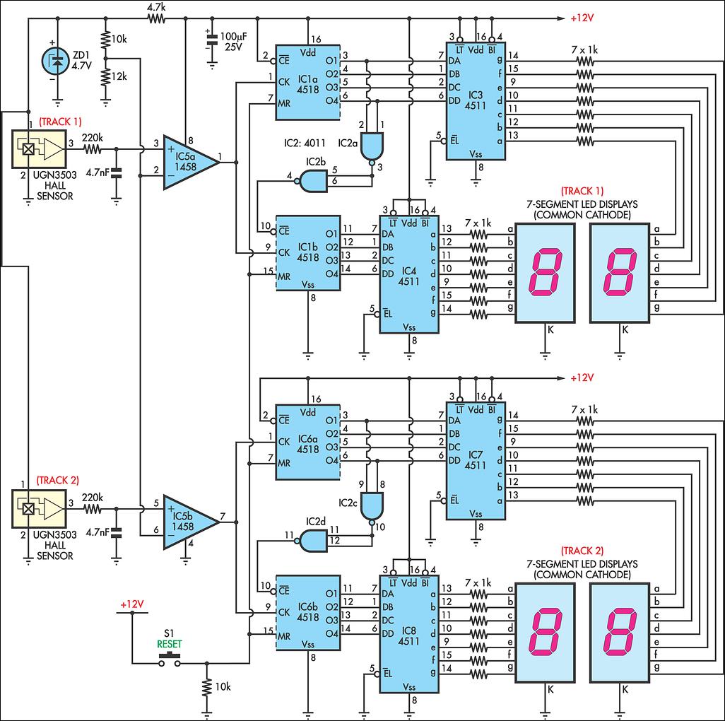
AFX slot car sets are enjoyable, and the experience can be enhanced with a lap counter. This circuit counts from 00 to 99, featuring independent counters for each track. The sensing device utilized is a Hall effect sensor (UGN3503;...
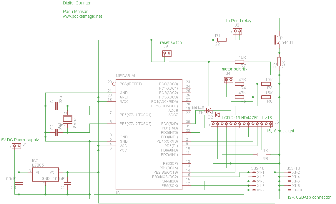
The circuit utilizes an Atmega8-8PU microcontroller configured for 8MHz operation with an external crystal oscillator. It incorporates a Nokia 5110 LCD and a transistor to manage the pulses generated by a reed relay. A 3.3V voltage regulator supplies power...

This is a CMOS-compatible (and ideally also TTL-compatible) input that includes over-voltage and under-voltage protection. Schmitt triggers are utilized to accommodate inputs with long transition times. It has been verified to function at frequencies up to 30 MHz. The described...
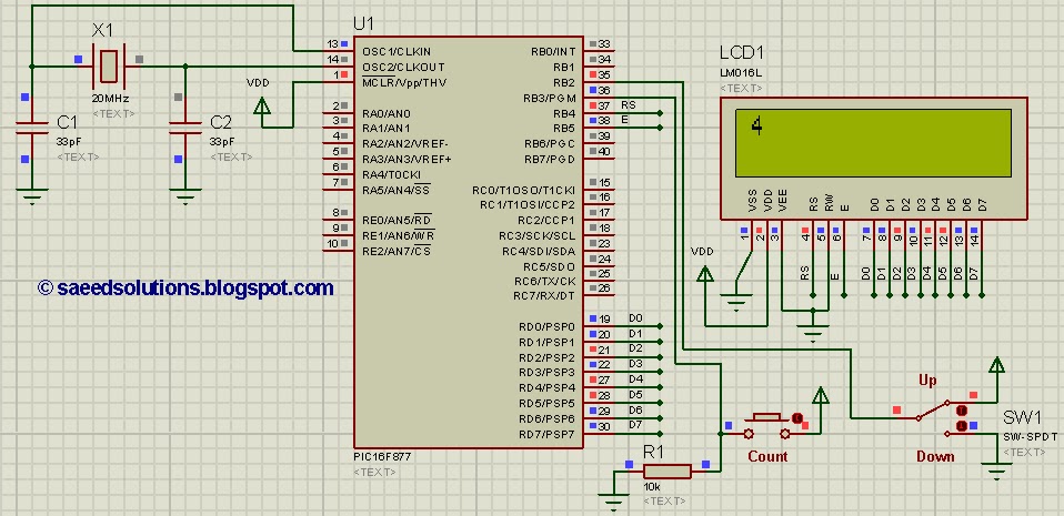
This tutorial on the PIC16F877 microcontroller addresses the implementation of an up-down counter using the PIC16F877. The process utilizes the PIC16 simulator (Proteus). The PIC16F877 microcontroller is a versatile device commonly used in various applications, including counter circuits. An up-down...
This clock timer utilizes a PIC16F628 microcontroller to display a 3.5-digit time format and control an external load. It is programmable to time intervals from 1 to 59 minutes. The clock features a calendar that accounts for leap years...
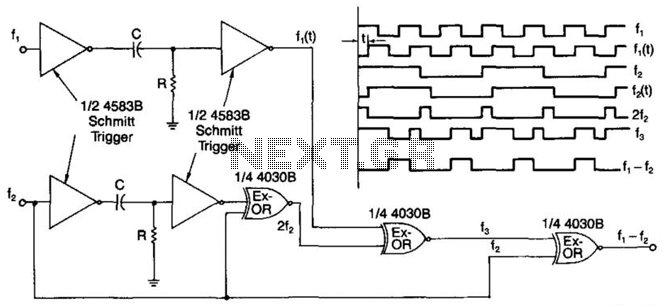
A simple digital mixer uses two dual-Schmitt triggers (4583B) and three exclusive-OR gates, incorporating an RC time-delay circuit to allow for easy adjustment of the output signal pulse width. The exclusive-OR gates can also function independently as a symmetrical...