
Digital Volt and Amp Meter


The circuit design utilizes a PIC Microchip Processor, specifically the PIC16F877A or PIC16F887, which is programmed to function as a volt and amp meter. The processor's internal 10-bit ADC is critical for measuring voltage and current accurately. The implementation requires careful calibration, especially when configuring the voltage divider formed by resistor R17 and variable resistor VR1. This voltage divider ensures that the input voltage to the ADC does not exceed the maximum limit of 5V, which is crucial to prevent damage to the microcontroller.
For current measurement, an operational amplifier (Op-Amp) is configured as an inverting amplifier. This setup amplifies the small voltage drop across the shunt resistor R7, which is placed in series with the load to be measured. The voltage drop is calculated based on Ohm's law, where the maximum expected current is 3A and the shunt resistance is 0.47 ohms. The output of the Op-Amp is then processed by the PIC to determine the actual current drawn by the load.
The voltage input to the PIC can be adjusted up to 33V, but the PIC only processes voltages from 0 to 5V. The scaling factor necessary for the ADC measurement is determined by dividing the maximum voltage by the resolution of the ADC (1024), resulting in a voltage increment of approximately 32.2mV per count.
To monitor temperature for cooling applications, an NTC thermistor is incorporated into the design. This thermistor is connected in series with a resistor (R19) to form a voltage divider, allowing the PIC to measure temperature changes and control a fan based on predetermined setpoints.
Display options include either an LCD compatible with HD44780 driver chips or a common anode 7-segment LED display. Configuration settings for voltage and current conversion factors can be adjusted via an RS232 terminal interface. The circuit also includes an IPSC connector for in-circuit programming of the PIC, and it operates with a power supply providing -12V, 0V, and +12V rails, ensuring adequate power for the entire system.The PIC Microchip Processor must be programmed before it will function as a Volt & Amp meter. There are many internet sites and PIC programmers that you can use. I used a Microchip MPLAB ICD 2 during the project. You might need to made changes to the circuit to accommodate a different type of programmer, do read the programmers instructions carefully. The circuit relies on the internal analogue to digital converter (ADC) of the PIC Microchip Processor.
The accuracy is dependant on scaling the input voltage for the ADC for all three measurements. The good news is that both the PIC's which can be used for this project have 10-Bit resolution ADC units which should work adequately in most circumstances. In order to determine the resolution, simple to advanced mathematics can be used - I will use simple mathematics and present a basic explanation in order for you to get going on the project. R17 and VR1 form a voltage divider as input to the ADC Input of the PIC. As the input voltage changes, so will the output of the Voltage divider on PIN 3 of the PIC. When calibrating the project for use it is important to remove the PIC from the circuit and adjust the Value of VR1 in such a manner that the output of the Voltage divider is never greater than 5.0V.
Failing to do so might damage the PIC. The current measurement is more complex and involves an Op-Amp configured as an inverting amplifier to provide the input for the PIC. The resistor R7, in the Power Supply circuit is used as a shunt resistor. The small voltage drop across the resistor varies according to the amount of current a given load will draw from the PSU.
In order to measure with greater accuracy the small voltage drop is amplified using an Op-Amp circuit. Using the formula for an inverting amplifier the output voltage of the Op-Amp can be calculated as follows: 1.
The maximum current through R7 maybe 3.0A 2. The voltage drop over R7 = V = I * R = 3.0A * 0.47R = 1.41V 3. Op-Amp output = Vout = -(R12/R16)(Vin) = -(33K/10K)/1.41V = -4.653V. However, the input is a negative voltage and if we negate the answer we should measure close to 4.653V for the maximum load. The Voltage of the PSU can be adjusted from 0 to 33V depending on the components in your circuit. The PIC can only measure voltages between 0 - 5V and represent the values measured as a 10bit binary number from 0 - 1024.
In order to determine the voltage increments which can be measured one has to divide the scaled input voltage by 1024 and that equals: 33V/1024 = 32.2mV. For cooling the main heatsink a third channel on the PIC's ADC is used to measure the temperature and control a small fan.
For this purpose a NTC Thermistor with a value of 10K is used. The NTC Thermistor is a device which reduces in resistance as the temperature increases. The same principal of a voltage divider is used to produce a voltage output which will allow the PIC to be used to determine the temperature measurement. The NTC Thermistor is connected in series with a 10K resistor R19 to produce a variable voltage output the PIC will compare to a setpoint to determine if the fan will be switched on.
Similarly the current range is 0 to 3A. Which means that we can measure in 3.0/1024 = 2.9mA increments in a near perfect circuit. Best Voltage resolution at 33.0V - 32.2mV Best Current resolution at 3.0A - 2.9mA Either a LED or LCD display can be used LCD Output is compatible with most LCD Displays with a HD44780 drive chip, it was designed for a 2 line x 16 character display 6 x 7 Segment LED Display using Common Anode displays Configuration via RS232 terminal to set Voltage and Current conversion factors Two PIC16F processors are supported, the 16F877A and 16F887 - separate hex files provided for download here IPSC Connector for Programming the PIC in circuit Separate -12V - 0 - +12V, Power Supply 🔗 External reference
Related Circuits
The +/- 3 dB point for the treble is approximately 2.5 kHz, with a boost/cut of about 12 dB at 10 kHz. It may be necessary to check the wiring or component values. Access to a signal generator is...
This ultra-bright white LED lamp operates on 230V AC with low power consumption. It is suitable for illuminating VU meters, SWR meters, and similar applications. The cost of ultra-bright LEDs available in the market ranges from Rs 8 to...
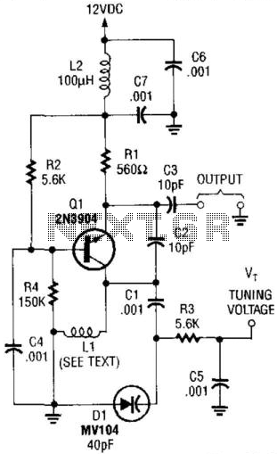
This VHF VCO circuit operates within the frequency range of 30 to 200 MHz. Q1 may be substituted with a 2N3563 for frequencies exceeding 100 MHz. The inductor, L1, is selected to resonate at the desired frequency in conjunction...
Measuring the temperature of coffee is important because the taste of coffee relies on two main factors: the strength of the coffee and its temperature. Measuring the temperature of coffee can be accomplished using a simple electronic circuit designed to...
This is a convenient and straightforward general-purpose 50-watt amplifier. The amplifier features an input for connecting devices such as radios, TVs, or stereo equipment. Additionally, it includes a phono input suitable for connecting record players, guitars, microphones, or other...
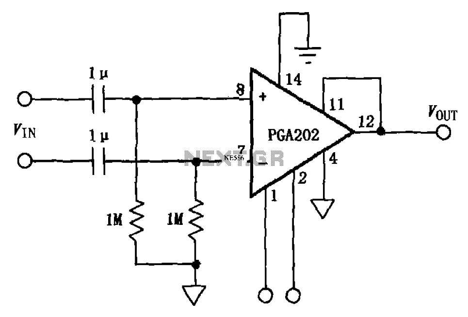
The circuit illustrated in FIG PGA202 comprises an AC-coupled differential amplifier. The input stage of PGA202 includes two 1 µF capacitors and two 1 MΩ resistors, resulting in a cutoff frequency of approximately 0.16 Hz. The Qualcomm AC coupling...