
Digital Voltmeter

The voltage-to-time conversion circuit is designed to accurately translate an analog voltage into a corresponding digital count, which represents the voltage level. The attenuation circuit serves to scale down the input voltage to a manageable level suitable for comparison with the ramp signal. The ramp generator produces a linear voltage ramp that increases over time, allowing for a straightforward comparison with the attenuated input signal.
The comparator C1 plays a crucial role in determining when the ramp voltage matches the input voltage. When the input voltage exceeds the ramp voltage, the output of C1 transitions low, signaling the start of the counting process. This transition is critical for timing applications where precise measurements of voltage levels are required.
The zero-crossing detector C2 is essential for identifying when the ramp voltage has returned to zero. This detection allows the system to know when to stop counting, ensuring that the count reflects only the duration in which the ramp voltage was less than the input voltage. The gating pulse, which is generated from the outputs of C1 and C2 along with the oscillator clock pulse, synchronizes the counting process, ensuring that counts are only registered during valid measurement intervals.
Finally, the display device connected to the counter provides a visual representation of the measured count, which corresponds to the input analog voltage. This conversion process is particularly useful in applications where analog signals need to be processed in digital systems, facilitating easier manipulation and analysis of the data. The entire system operates in a controlled manner, ensuring accuracy and reliability in the conversion of analog voltages to digital counts.In the voltage to time conversion section, the analog input voltage is fed to the attenuation circuit. The attenuated signal is compared with the the ramp signal generated by the ramp generator given in the block diagram by the input comparator `C1`.
Similarly, The ramp signal generated is compared with 0V via a zero-crossing detector `C2`. A sample rate multivibrator is connected to the ramp generator whose purpose is to provide an initiating pulse for the ramp generator to start the next ramp voltage for the next measurement. It is also used to reset the counter before generating the next ramp voltage. In the time measurement section, there is counter which is triggered by a gating pulse. The inputs of the gating pulse are (i) Output of `C1` (ii) Output of `C2` (iii) Clock pulse from the oscillator.
The counter is reset after each successful completion of time measurement by a control signal from the sample rate multivibrator. The count produced is displayed by connecting suitable display device. Initially, the attenuated signal is compared with a negative going ramp signal generated by the ramp generator.
When the ramp voltage coincides with the input signal, the output of `C1` becomes low. This point is called coincidence point. This initiates the counting process ( start of count ). The counter continues to count until the ramp voltage reduces and crosses zero (0V). This is detected by zero crossing detector `C2`. The output of `C2` becomes high which ends the counting process (end of count). The count displayed is the count of number of clock pulses produced by the oscillator during the time in which the ramp signal is less than the input signal and greater than 0V (ie) |input signal| > ramp > 0V. This count gives the digital equivalent of input analog voltage. 🔗 External reference
Related Circuits
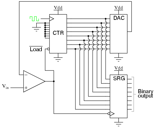
Also known as the stairstep-ramp or simply counter A/D converter, this type of converter is relatively straightforward to comprehend but unfortunately has several limitations. The stairstep-ramp or counter A/D converter operates on the principle of comparing an analog input voltage...
This standalone digital thermometer regulates the temperature of a device based on its requirements. It displays the temperature on four 7-segment displays, with a range from 55 to +125 °C. The core of the circuit is the AT89S52 microcontroller,...
The diagram illustrates a block diagram for an agenda alarm and agenda thermometer system. It includes one temperature sensor, a real-time clock (RTC), a microcontroller (PIC), an EEPROM, a 7-segment display, and a keyboard. The EEPROM is utilized to...
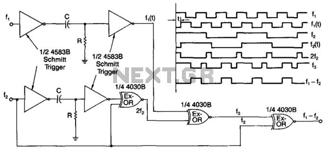
A simple digital mixer uses two dual-Schmitt triggers (4583B) and three exclusive-OR gates, incorporating an RC time-delay circuit to allow for easy adjustment of the output signal pulse width. The exclusive-OR gates can also function independently as a symmetrical...
The Clock Controller was designed to be an exemplary of using 'C' language to control timer0 interrupt, 7-segment LED and keypad scanning. It provides 1-bit sink current driving output, for driving a relay, opto-triac, say. Many projects requiring 7-segment...
U1 is a 3817 integrated circuit produced by Fairchild Corporation. It is capable of directly driving a display and can operate in both 12-hour and 24-hour formats. Additionally, it can generate a clock sound and activate radios at scheduled...