
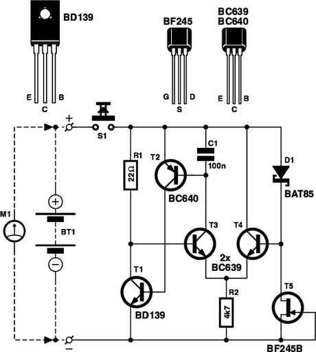
Logic test probe with memory

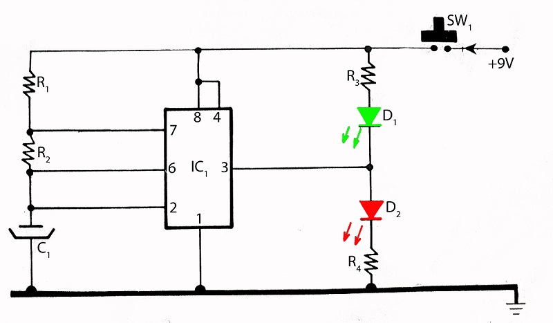
The circuit features two primary control elements: a memory disable switch and a pulse polarity switch. The memory disable switch is implemented as a momentary push-button switch. When activated, this switch generates a signal that resets the memory element of the circuit to a low state, effectively clearing any stored data or states. This function is crucial for applications requiring a fresh start or for troubleshooting purposes.
The pulse polarity switch, on the other hand, is a toggle switch that allows the user to select between two operational modes for the probe. One position of the switch configures the probe to respond to a high-level signal, specifically a +5 V pulse, which is commonly used in digital logic circuits to represent a logical '1'. The alternative position configures the probe to respond to a low-level signal, typically ground (0 V), representing a logical '0'. This versatility is essential for testing and verifying the behavior of integrated circuits (ICs) under different logic levels.
For effective operation, it is recommended to utilize integrated circuit (IC) logic that matches the type of logic being tested. This ensures compatibility and accurate performance during testing procedures. The circuit design should consider the specifications of the ICs used, including their input and output voltage levels, current requirements, and response times, to ensure reliable operation across various testing scenarios.
Overall, this circuit design provides a straightforward yet effective means of controlling memory states and signal polarity, making it a valuable tool for electronics testing and development.There are two switches: a memory disable switch and a pulse polarity switch. Memory disable is a push-button that resets the memory to the low state when depressed. Pulse polarity is a toggle switch that selects whether the probe responds to a high-level or pulse (+5 V) or a low-level or pulse (ground) (Use IC logic of the same type as is being tested).
Related Circuits
Is the battery depleted, or is there an issue with the device? This question often arises when a battery-operated device, such as a Walkman, fails to power on. Before seeking professional repair services, it is advisable to first test...

The Unit is started by hand by revolving the two disks in opposite directions and continues to move without further input. This device has only two moving parts namely the bearing races at the centre of the disk. The...
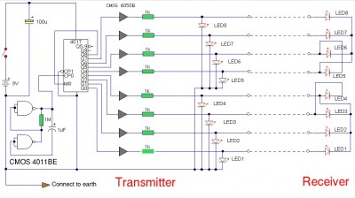
The LAN tester circuit can also test cables such as telephone, coaxial, LAN, and others. This circuit uses LEDs as the main indicator device. The LAN tester circuit is designed to verify the integrity and functionality of various types of...
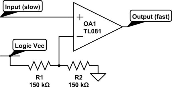
Invert a signal to drive FETs with rapid rise and fall times. It was suggested to use an inverter (not a chip) instead of logic chips, which are designed to be either fully ON or OFF. The individual has...
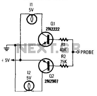
By connecting this circuit to a powered logic device, an indication of its status can be obtained. If the circuit is open, neither of the test lamps will illuminate. If the circuit is grounded, the low (or zero) lamp...
The integrated circuit (IC) tester featured on this website is specifically designed for the LM555 timer IC. This circuit is utilized for testing the functionality of the timer IC, and it includes a circuit diagram along with techniques for...